SkyTrak 3606 Service Manual User Manual
Page 100
Section 4
4-14
Joystick Handle Installation
1. Apply Loctite
®
#272 (red) to the threaded stud on the
joystick handle. Position the joystick mounting stud
into the base mounting hole and turn the handle to
thread it into the base. Align the joystick in the
forward position.
2. Secure the joystick by tightening the mounting nut
(jam nut) at the threaded end of the joystick onto the
threaded shaft in the joystick assembly base.
3. Connect the joystick wire lead to the logic board plug
and install the rubber boot over the joystick.
4. Check for proper operation of all joystick functions.
B. Joystick Assembly Replacement
Joystick Assembly Removal
1. Park the vehicle on a firm, level surface. Set the park
brake, ground the carriage, place the transmission in
NEUTRAL (N) and turn the ignition OFF.
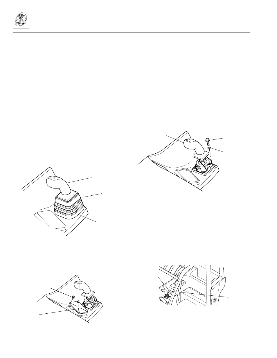
2. Remove the boot from the joystick by pulling the boot
off the base (Fig. 4–14).
Figure 4–14. Remove the boot from the joystick.
3. Remove the four button-head capscrews holding the
logic panel to the side console (Fig. 4–15). Carefully
pry the logic console upward. Label, then disconnect
the wiring harness leads at the logic panel. Remove
the logic panel from the vehicle.
Figure 4–15. Remove the four button-head capscrews.
IMPORTANT: Before proceeding, determine which type
of joystick mounting fasteners are used. Reach into the
logic panel opening and back toward the joystick. From
inside the console, feel along the front lower edge of the
joystick base to determine whether "long" internally-
threaded hex nuts are installed, or if nutserts are used.
If long hex nuts are used, go to step 5 and follow the
steps for Early Production Vehicles. If nutserts are used,
go to step 4 and follow the steps for Current Production
Vehicles.
4. Current Production Vehicles
Remove the three flange-head capscrews and
lockwashers securing the joystick assembly to its
mounting hole in the side console (Fig. 4–16). Save
the three flange-head capscrews and lockwashers for
reuse later. GO TO STEP 11.
Figure 4–16. For Current Production Vehicles, remove
the flange-head capscrews and lockwashers securing
the joystick assembly to the console.
5. Early Production Vehicles
Pry the entire switch bezel out and away from the
side console (Fig. 4–17). Label, then disconnect the
wiring harness leads at the switches. Remove the
switch bezel from the vehicle.
Figure 4–17. For Early Production Vehicles,
remove the switch bezel from the vehicle.
SS1190
Joystick
Boot
Base
Button-head
Capscrew
Logic Panel
SS1210
SS1200
Lockwasher
Flange-head
Capscrew
Joystick
SS1220
Switch
Bezel
Side
Console
Model 3606
•
Origin 10/99