Stabil-trak hydraulic circuit -34, Frame tilt/stabilizer legend – SkyTrak 3606 Service Manual User Manual
Page 228
Section 9
9-34
Model 3606 • Origin 10/99
9.8.5
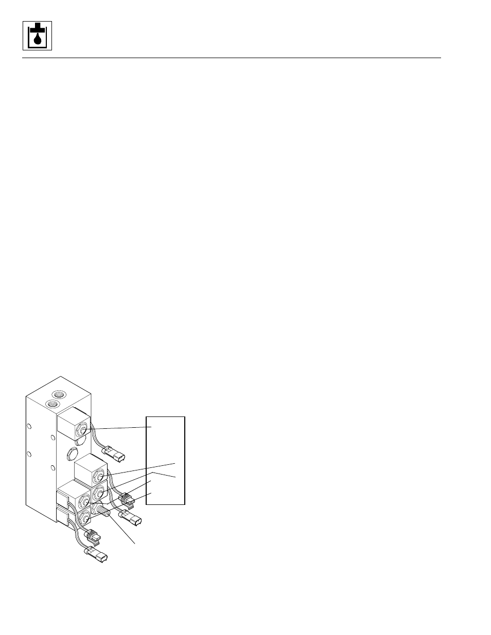
Stabil-TRAK Hydraulic Circuit
a. Stabil-TRAK System
The patented rear axle lock or Stabil-TRAK system works
to stabilize the vehicle under various conditions. The SKY
TRAK Owners/Operators Manual Model 3606 contains
basic Stabil-TRAK information; a copy of the owners/
operators manual should always be available in the stor-
age compartment beneath the operators seat.
The stabilizing system operates via an interface between
the boom proximity switch, the park brake, service brake
and travel select lever hydraulic and electrical circuits,
and five solenoid-operated valves on the Stabil-TRAK
manifold (Fig. 9– 23) mounted on the left side of the rear
axle.
The frame tilt cylinder is also involved in the Stabil-TRAK
system, but only passively as hydraulic fluid is cycled to
accommodate Stabil-TRAK system operation.
The rear axle lock system can only be activated when the
boom angle is greater than 40 degrees. Any one, any two
or all three of the following selections will activate the
system:
• Engaging the Parking Brake Switch
• Placing the Travel Select Lever in (N) NEUTRAL
• Depressing and holding the Service Brake
With the boom lowered to an angle of less than 40
degrees, the rear axle lock system is not active and none
of these functions will affect the rear axle lock system.
Figure 9– 23. Stabil-TRAK manifold.
Frame Tilt/Stabilizer Legend
1. Stabil-TRAK Manifold
2. Dual Pilot Operated Check Manifold
3. Tie Wrap
4. Hose, 3/8” I.D. x 158”
5. Hose, 3/8” I.D. x 104”
6. Hose, 3/8” I.D. x 160”
7. Hose, 3/8” I.D. x 93”
8. Hose, 3/8” I.D. x 117”
9. 90° Elbow, SAE 6 - Str. Thd. ORB x O-Ring Face Seal
10. Connector, SAE 6 - Str. Thd. ORB x O-Ring Face Seal
11. Swivel Elbow, SAE 6, O-Ring Face Seal
12. Lockwasher, SAE 3/8”
13. Lockwasher, 3/8”
14. Grade 8 Hex-head Capscrew, 3/8-16 x 3-3/4”
15. Grade 8 Hex-head Capscrew, 3/8-16 x 4-3/4”
16. Branch Tee, SAE 8 - Str. Thd. ORB x O-Ring Face Seal
17. 90° Swivel Elbow, SAE 8, O-Ring Face Seal
(w/o Aux. Hyd. option)
Swivel Run Tee, SAE 8, O-Ring Face Seal
(w/ Aux. Hyd. option)
18. Long Connector, SAE 8 - Str. Thd. ORB x O-Ring Face Seal
19. Connector, SAE 6-8 - Str. Thd. ORB x O-Ring Face Seal
20. Swivel Branch Tee, SAE 16, ORB x O-Ring Face Seal
21. Reducer, SAE 16,
O-Ring Face Seal x SAE 8 O-Ring Face Seal
22. Tube Nut, SAE 16, O-Ring Face Seal
23. Connector, SAE 16-12 - Str. Thd. ORB x O-Ring Face Seal
24. Hex-head Plug, SAE 4, Male Str. Thd. O-Ring
25. Manifold
26. O-Ring
27. Socket-head Capscrew, 3/8-16 x 1-1/2”
28. Hex-head Plug, SAE 6, Male Str. Thd. O-Ring
29. Connector, SAE 8-6 - Str. Thd. ORB x O-Ring Face Seal
30. 90° Swivel Elbow, SAE 8, O-Ring Face Seal
31. Reducer, SAE 8,
O-Ring Face Seal x SAE 6 O-Ring Face Seal
32. Hex-head Capscrew, 5/16-18 x 1-1/4”
33. Lockwasher, 5/16”
34. Twin Clamp Cover
35. Twin Hose Clamp Set, 0.68” I.D.
36. Stacking Bolt, 5/8” Long
37. Stacking Bolt, 1-1/8” Long
38. Locking Plate
39. Twin Hose Clamp Set, 0.78” I.D.
40. Grade 8 Hex-head Capscrew, 5/16-18 x 1-1/2”
41. Tie Wrap
42. Loctite
®
, 0.5 ounce
FT
R
MS1930
4
100 psi (7 bar)
Pressure-reducing
Valve
Solenoid/circuit
numbers