SkyTrak 3606 Service Manual User Manual
Page 376
Section 10
10-58
Model 3606 • Origin 10/99
a. Fuel Run Solenoid Removal
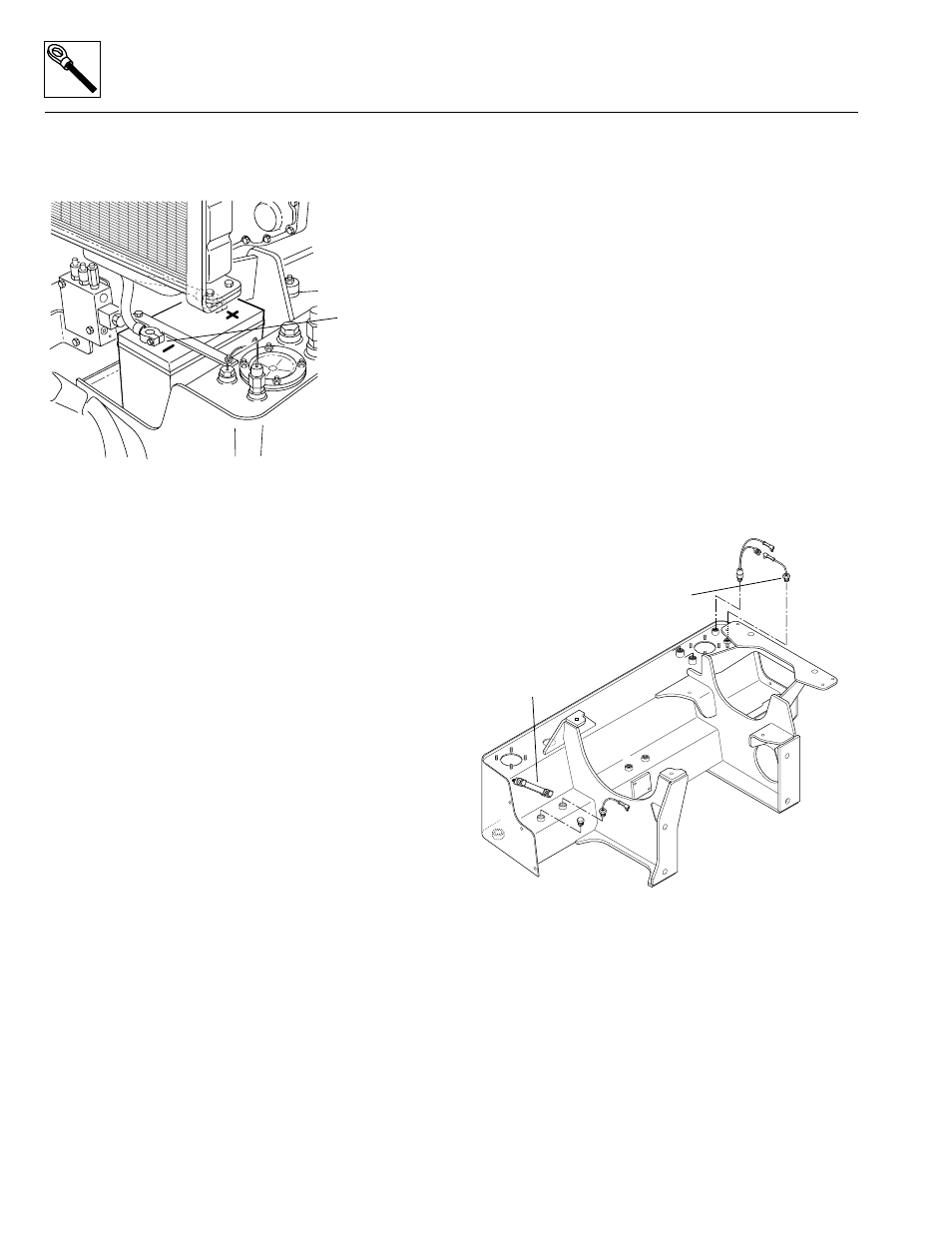
1. Disconnect the negative (-) battery cable at the
negative battery terminal (Fig. 10– 59).
Figure 10– 59. Disconnect the negative (-) battery cable
at the negative (-) battery terminal.
2. Disconnect the wiring connector at the fuel run
solenoid lead, then remove the fuel run solenoid from
the fuel injector pump.
3. For Perkins engines: Use a wrench to remove the
solenoid.
For Cummins engines: Remove the two bolts
securing the solenoid to the mounting plate. Remove
the nut holding the linkage to the arm on the fuel
injection pump. Save the hardware for later re-use.
b. Fuel Run Solenoid Disassembly
DO NOT disassemble a fuel run solenoid. Replace a
defective fuel run solenoid with a new one.
c. Fuel Run Solenoid Inspection and Replacement
Use a 12-volt DC source and ground to test the solenoid.
Energize the solenoid and watch for the plunger to
retract. If the plunger does not retract, replace the fuel
run solenoid with a new one.
d. Fuel Run Solenoid Installation
1. Clean the exterior of the fuel injector pump.
2. For Perkins engines: Install a new O-ring on the fuel
run solenoid (2, Fig. 10– 57). Install the fuel run
solenoid onto the fuel injector pump (1). Use a
wrench to install the solenoid. DO NOT overtighten.
For Cummins engines: Using the hardware removed
earlier, install the nut holding the linkage to the arm
on the fuel injection pump (2, Fig. 10– 58). Install the
two bolts to secure the solenoid to the mounting
plate.
3. Connect the wiring connector at the fuel run solenoid
lead.
4. Connect the negative (-) battery cable to the negative
battery terminal (Fig. 10– 59).
5. Clear personnel and any obstructions from the area
around the vehicle.
6. Start the engine.
7. If the engine starts, the fuel run solenoid is
functioning.
8. If the engine fails to start, the fuel run solenoid may
have a poor ground connection. Visually check the
wiring at the fuel run solenoid leads and/or check for
continuity with a voltmeter as required.
9. Check for fuel and/or oil leakage around the solenoid.
10.8.6 Hydraulic Oil Filter Pressure Switch
The hydraulic oil filter pressure switch (Fig. 10– 60) is
threaded into a fitting welded at the top rear of the
hydraulic oil reservoir.
Figure 10– 60. Location of the hydraulic oil filter
pressure switch, hydraulic temperature switch,
and hydraulic oil sight glass.
The switch is connected to the wiring harness and to the
hydraulic oil temperature switch. When the 25 psi
(1,7 kPa) hydraulic oil system filter is clogged or
restricted and the internal pressure of the filter rises to 25
psi (1,7 kPa), the switch closes and the hydraulic oil filter
restriction indicator illuminates on the operators display
panel. The vehicle should be stopped and the engine
revved at high idle for five minutes. If the light remains
illuminated or begins to flicker on and off at high idle, shut
down the engine and inspect the hydraulic system.
OS1040
Negative (-)
Terminal
MS1700
Pressure Switch
Temperature Switch
Sight Glass