Cummins engine – SkyTrak 3606 Service Manual User Manual
Page 189
Cummins Engine
8B-19
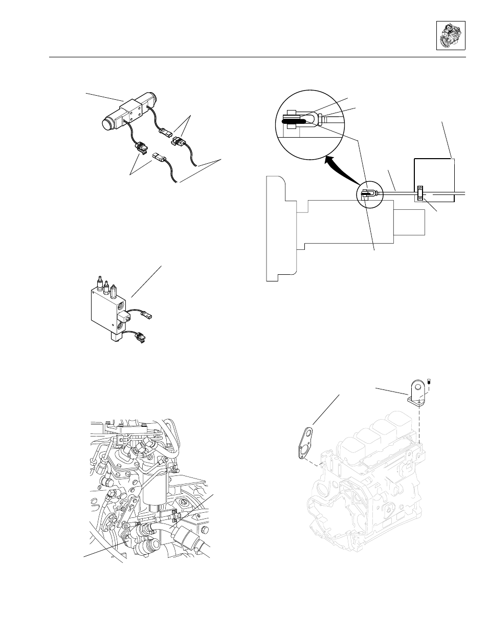
17. Label and disconnect the wiring harness at the steer
select valve (Fig. 8B–18).
Figure 8B–18. Label and disconnect the wiring
at the steer select valve.
18. Label and disconnect the wiring connectors at the
auxiliary function valve solenoids (Fig. 8B–19). Move
all wiring out of the way to allow engine removal.
Figure 8B–19. Disconnect the wiring at the auxiliary
function valve solenoids.
19. Working from the side of the vehicle, disconnect the
fuel return line at the fuel injector pump.
20. Disconnect the fuel inlet line (Fig. 8B–20) at the fuel
lift pump.
Figure 8B–20. Fuel inlet line to lift pump connection.
21. Mark the location of the throttle cable at its engine
mount bracket (Fig. 8B–21).
Figure 8B–21. Throttle cable connection at engine.
22. Disconnect the throttle cable (Fig. 8B–21) at the
bracket above the starter.
23. At the hydraulic fluid reservoir, disconnect the engine
harness wire lead (Fig. 8B–11) from the hydraulic
fluid-level sending unit.
24. Connect a suitable engine hoist to the engine lift
plates (Fig. 8B–22).
Figure 8B–22. Typical engine lift plates.
MS1400
Steer select valve
Disconnect
Engine
wiring
harness
leads
Disconnect
T
PB
PB
G
OS0731
Auxiliary function valve
(also see Fig. 8B-11)
OS1430
Fuel inlet
line
Fuel lift
pump
MA0201
Two washers
Jam nut
Bracket
(above starter)
Stop and throttle lever
Throttle
cable
Clamp
Clevis, clevis pin
and cotter pin
INJECTOR PUMP
MA2030
Engine
lift plates
Model 3606 • Origin 10/99