In fig. 9–10. t – SkyTrak 3606 Service Manual User Manual
Page 209
Hydraulic System
9-15
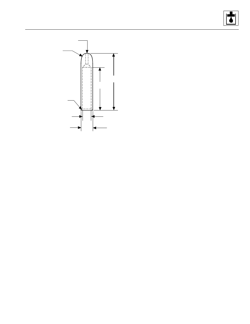
Figure 9– 10. Special steel sleeve dimensions.
5. A lip seal installation bar, made from round steel bar
stock 1-3/4" (44,45mm) in diameter by 2" (50,8mm)
long. Grind the edges slightly to form the tool.
6. The following tools will also be required:
• arbor press
• awl
• clean, lintless cloths
• metal deburring tool
• machinist's hammer
• soft hammer
• non-hardening sealant
(Permatex
®
Aviation Form-A-Gasket No. 3)
or equivalent
• medium-grit Carborundum stone
• oil and grease
• snap-ring pliers
• scale, 1/32" (0,79mm)
or 1/64" (0,40mm) graduations
• small screwdriver
• torque wrench
• vise with 8" minimum open spread
c. General Repair Precautions
1. To facilitate repair of the pump and before any work is
done, first, read and understand all of the steps used
in the disassembly and assembly instructions.
2. The first requirement of good hydraulic equipment
maintenance is cleanliness. Perform procedures in a
clean area.
3. If it becomes necessary to pry sections apart, be
extremely careful to avoid damaging the finely-
machined surfaces. Excessive force used while
prying can result in misalignment and serious
damage to parts.
4. Match-mark the exterior surfaces of any housings
before separating the components. Use the marks to
return components to their original location during
assembly.
5. Gears are closely-matched sets which wear in
together. Keep gears together as sets when
removing them from a unit. Handle gears with care to
avoid damaging the journals or teeth. Avoid touching
gear journals. Always replace matched parts as a
set.
6. To help prevent damage, DO NOT grip machined
surfaces in a vise.
7. If parts are difficult to fit together during assembly,
tap gently with a soft hammer. NEVER use an iron or
steel hammer to tap parts.
8. NEVER hammer bushings into bores. Use an arbor
press and bushing drivers of appropriate sizes to
install bushings.
d. Pump Disassembly (Fig. 9– 11)
1. Secure the pump with the pump drive shaft pointing
down in a suitable holding device or bench vise if
possible. Scribe or otherwise make a mark across
the two pump housings (4 and 13, Fig. 9– 11) and the
gear housing (11) perpendicular to the parting lines
for easy identification and proper alignment during
assembly later.
2. Remove the four capscrews (3) and washers (2) that
secure the two pump housings (4 and 13) together.
3. Carefully separate the pump housings (4 and 13)
from the gear housing (11). If it becomes necessary
to pry the components apart, proceed carefully and
DO NOT damage the machined surfaces or internal
components. Dowel pins (5) will remain installed in
most cases; however, DO NOT remove dowel pins
unless they are damaged.
4. Remove the square “R” seal (10), channel seals (8),
backup seals (7) and thrust plates (9).
A
B
C RADIUS
0.015" X 45°
CHAMFER
E
D
A 3-3/8"
B 4-1/2"
C 9/16" R
D 1.065 PLUS 0.000, MINUS 0.002"
E 1.002 PLUS 0.002, MINUS 0.000"
1/4" DIAMETER DRILL
THROUGH HOLE
MA0821
Model 3606 • Origin 10/99