Section 9
9-52
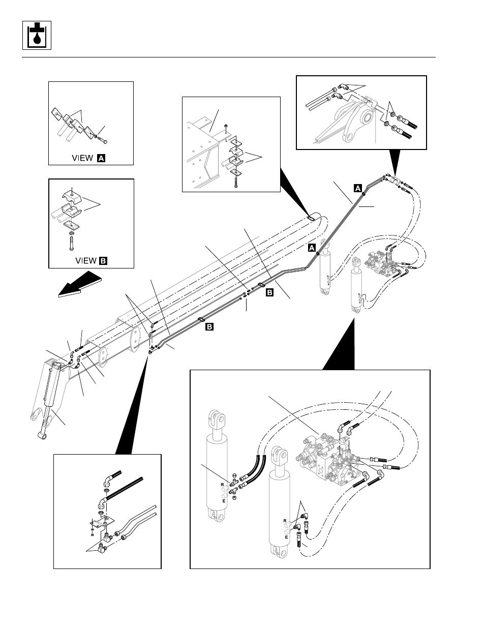
Figure 9– 40. Attachment tilt/slave cylinder circuit.
3
3
1
2
3
4
5
6
7
8
9
10
11
12
13
14
15
16
17
18
19
20
21
22
23
24
25
26
27
29
1
1
1
2
3
7
11
14
15
16
15
16
17
18
20
22
22
22
22
21
23
20
24
29
27
28
28
29
Inner Boom
Inner tube
under boom
Inner tube
at bulkhead
Outer tube
at bulkhead
Outer tube
under boom
Front of Vehicle
Attachment
Tilt Cylinder
Main Control Valve
Assembly (ref.)
RH
LH
PS0390
Model 3606 • Origin 10/99