Transfer case maintenance, Transfer case removal, Internal transfer case repair – SkyTrak 3606 Service Manual User Manual
Page 129
Transfer Case and Drive Shafts
6-5
6.3.2 Transfer Case Maintenance
Information regarding checking the transfer case oil
level and/or changing the transfer case oil is located in
Section 2.12.13 Transfer Case Oil.
6.3.3 Transfer Case Removal
1. Level the vehicle, ground the carriage, place the
travel select lever in NEUTRAL (N), engage the
parking brake switch and shut the engine OFF. Allow
the engine to cool.
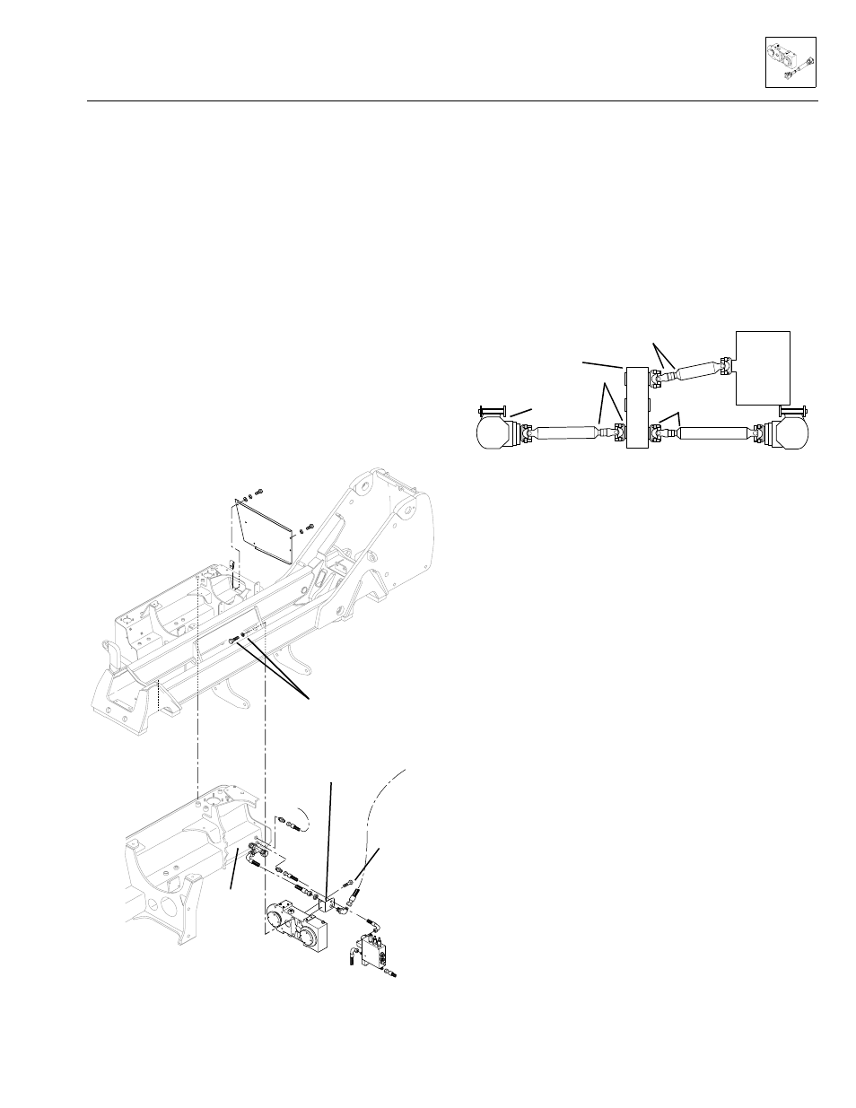
2. Remove the engine mount rear cover plate (Fig. 6–2).
3. Unbolt and remove the two M8 bolts securing the
bulkhead fitting bracket to the transfer case. Safely
swing the bracket and the hydraulic hoses out of the
way to help prevent interference with removing the
transfer case and drive shafts. Reinstall the bolts
securing the left side of the center transfer case
cover plate to the transfer case.
Figure 6–2. Transfer case mounting arrangement.
IMPORTANT: To help ensure optimum performance, the
drive shaft assemblies are specially balanced as a unit at
the factory. When servicing any flange yoke, slip yoke, or
drive shaft tube, order a complete assembly if components
are bent or damaged. Refer to the Sky Trak International
Model 3606 Parts Manual for ordering information.
4. For reference, mark the transmission input drive shaft
and flange yoke at the transfer case for return to their
original positions upon reinstallation (Fig. 6–3).
Unbolt the flange yokes from the transmission and
from the transfer box. Move the drive shaft out of the
way to allow clearance for transfer case removal.
Figure 6–3. Mark the shafts and yokes for return to their
original positions.
5. For reference, mark the front and rear axle output
drive shafts and transfer case for return to their
original positions upon reinstallation (Fig. 6–3).
Unbolt the flange yokes from the axles and from the
transfer box. Move the drive shaft out of the way to
allow clearance for transfer case removal.
6. Position a transmission jack or suitable lifting device
beneath the transfer case. Operate the jack to
contact and support the transfer case, but DO NOT
jack up or raise the transfer case itself. Secure the
transfer case to the jack or lifting device with a sling.
7. Unbolt the M16 bolts and lock washers (Fig. 6–2)
securing the transfer case to the vehicle chassis.
Carefully lower the transfer case and remove it from
beneath the vehicle.
6.3.4 Internal Transfer Case Repair
Detailed transfer case service instructions covering
repair, disassembly, reassembly, adjustment and trouble-
shooting information are provided in the Carraro Model
TB 420 Transfer Box Maintenance and Repair Manual,
Carraro part number CA355026.
Engine mount
rear cover plate
Engine mount
(subframe)
Vehicle
chassis
M16 bolt and lock-
washer (4 each)
Bulkhead fitting
bracket
M8 bolt (2)
Transfer case
Reservoir
Engine mount
(subframe)
MS0490
MS0710
Mark Position
Transfer Case
Mark position
Rear Axle
Mark
position
Trans-
mission
Bottom view facing up
Model 3606 • Origin 10/99