Wiring to each terminal, Flow transmitter, Bulletin f-107-uxf3 – Dwyer UXF3 User Manual
Page 23
-15-
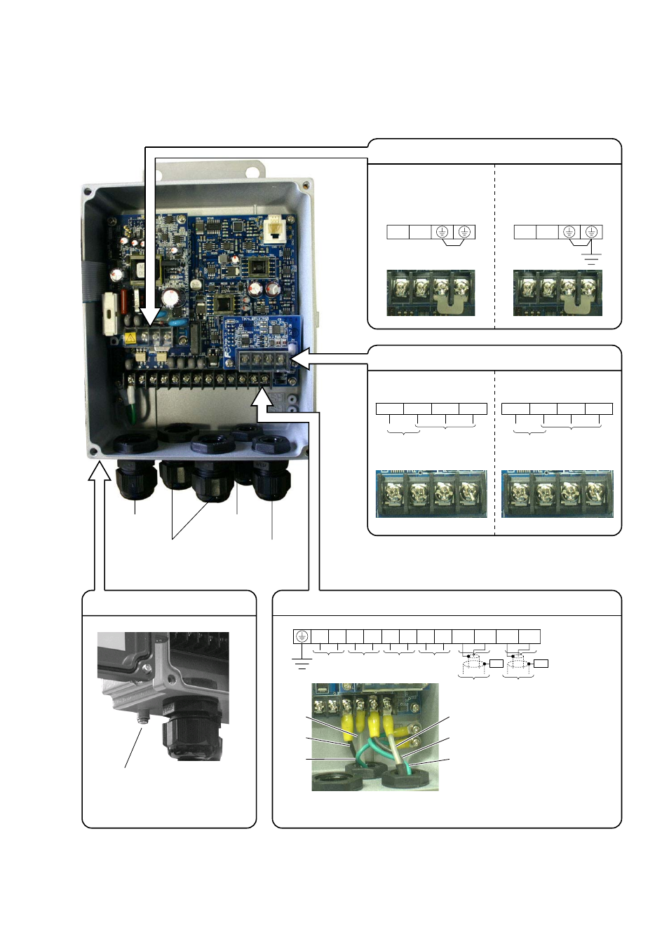
3.4.4. Wiring to each terminal
3.4.4.1. Flow transmitter :
Carry out wiring to each terminal according to the following figure.
External ground terminal
Power supply board terminal block
AC power supply
100 to 120V AC
or 200 to 240V AC
50/60Hz
Power cable
Downstream
sensor cable
Upstream
sensor cable
Output signal cable
(analog output, DO1,
DO2, DO3, DI)
Ground terminal (M4)
Main board terminal block
Iout
: Analog output
DO1, 2 : Transistor/open collector
DO3
: Relay contact
+
−
−
+
DO1
DO2
DO3
+
−
+
−
I out
To upstream
sensor
White
Black
Green
White
Black
Green
To downstream
sensor
GND HF1
HF2
GND
N
L
DC power supply
20 to 30V DC
−
+
Communication board terminal block (option)
RS-232C and DI
RS-485 and DI
TXDR1
SHILD
RS-485
TXDR2
DI1
Status input
Non-voltage contact input
TXD
DI1
GND
RXD
RS-232C
Note)
Note) When you use optional PC communication loader cable,
connect the cable of which terminal cap is black to GND,
yellow to RXD and red to TXD.
Status input
Non-voltage contact input
*1
*1
SH
SH
To downstream
sensor
To upstream
sensor
Note 1) All screws are M3 on the terminal block. Use crimp-style terminals for M3 and whose outer diameter is
Ɏ5.8 or
smaller.
Note 2) Be sure to connect ground terminal to external ground terminal. (Class D grounding)
Note 3) For output signal, use multiple core cable as required.
Bulletin F-107-UXF3