Dwyer PAFS-1000 User Manual
Dwyer instruments, inc, Series pafs-1000 averaging flow sensor, Bulletin pafs-1000
The Series PAFS-1000 Averaging Flow Sensor from Dwyer Instruments, Inc. is
ideal for sensing differential pressure in the inlet section of variable air volume
terminal units and fan terminal units. Units can also be used to sense differential
pressure at other locations in the main or branch duct systems.
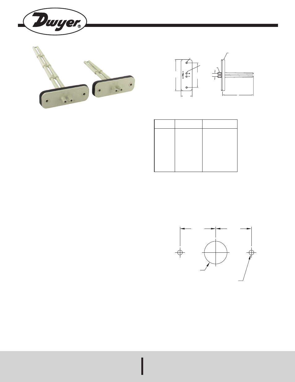
The “H” port senses total pressure and the “L” port senses static pressure. The
difference between these signals is the differential, or velocity pressure.
Models offer up to ten sensing points and lengths of 3-5/32˝ to 23-29/32˝ (8.02 to
60.72 cm) to accommodate box sizes of 4˝ to 30˝ (10.16 to 76.20 cm).
INSTALLATION
The Series PAFS-1000 utilizes 1/4˝ ID, 3/8˝ OD tubing. First check that there are
no sharp bends in the tubing at any connection. Bends and creases may leak over
time as the tubing ages.
Connect the “H” Port to the high input on the differential pressure gage, transmitter,
or switch.
Connect the “L” Port to the low input on the differential pressure gage, transmitter,
or switch.
Approximate K factors for models:
PAFS-1002: 1.32
PAFS-1003: 1.39
PAFS-1004: 1.46
PAFS-1005: 1.46
PAFS-1006: 1.58
PAFS-1007: 1.67
PAFS-1008: 1.78
PAFS-1009: 1.88
PAFS-1010: 2.01
PAFS-1011: 2.14
It may be necessary to calibrate in order to insure an accurate measurement.
You can do this by completing a traverse of the duct or fan to determine the delta
P sensed by the PAFS vs. the actual flow.
MOUNTING
1. Install the unit horizontally to assure accurate velocity readings for units ranging
from 3-5/32˝ to 9-29/32˝. If using a unit longer than the PAFS-1005, which is 9-
29/32˝, vertical mounting is recommended.
2. Determine the duct’s flow direction and install the Series PAFS-1000 based on
the unit’s flow arrow imprint.
3. Cut a 7/8˝ hole in the ducting to accept the unit.
4. Attach using two self-tapping screws inserted in the 3/16˝ mounting holes.
Series PAFS-1000 Averaging Flow Sensor
Specifications -Installation and Operating Instructions
Bulletin PAFS-1000
DWYER INSTRUMENTS, INC.
Phone: 219/879-8000
www.dwyer-inst.com
P.O. BOX 373 • MICHIGAN CITY, INDIANA 46360, U.S.A.
Fax: 219/872-9057
e-mail: [email protected]
SPECIFICATIONS
Service: Air and compatible gases.
Wetted Materials: ABS/polycarbonate (UL94-5V).
Temperature Limits:
Operating: 40 to 120°F (4 to 49°C);
Storage: -40 to 140°F (-40 to 60°C).
Connection: 1/4˝ (6 mm) ID, 3/8˝ (10 mm) OD tubing.
Mounting Orientation: Integral flange with gasket.
Weight: 1 oz (28 g).
3-1/2
[88.90]
1-1/4
[31.75]
2-3/4
[69.85]
FOAM GASKET
1/8 THK
[6.35 THK]
A
PUSH-ON
CONNECTIONS
FOR 3/8
POLY TUBING
[9.53 OD]
MOUNTING HOLES
2XШ3/16 [Ш4.76]
7/16
[11.11]
Model
PAFS-1002
PAFS-1003
PAFS-1004
PAFS-1005
PAFS-1006
PAFS-1007
PAFS-1008
PAFS-1009
PAFS-1010
PAFS-1011
Number of
Sensing Points
1
2
3
4
5
6
7
8
9
10
DIMENSIONS
Sensor
Length
3-5/32˝ (8.02 cm)
5-13/32˝ (13.73 cm)
7-21/32˝ (19.55 cm)
9-29/32˝ (25.26 cm)
12-1/2˝ (31.75 cm)
14-3/4˝ (37.47 cm)
17-1/8˝ (43.50 cm)
19-13/32˝ (49.29 cm)
21-21/32˝ (55.01 cm)
23-29/32˝ (60.72 cm)
©Copyright 2010 Dwyer Instruments, Inc.
Printed in U.S.A. 12/13
FR# 72-443834-00 Rev.1
MOUNTING DETAILS
MAINTENANCE
Sensing orifices must be kept free of dust accumulation or debris. Occasional
cleaning may be required.
Upon final installation of the Series PAFS-1000 Averaging Flow Sensor, no routine
maintenance is required. A periodic check of system calibration is recommended.
The Series PAFS-1000 is not field serviceable and should be returned if repair is
needed (field repair should not be attempted and may void warranty). Be sure to
include a brief description of the problem plus any relevant application notes.
Contact customer service to receive a return goods authorization number before
shipping.
1-3/8˝
[35]
1-3/8˝
[35]
7/8˝ [22] DIA
CLEARANCE HOLE
(2) 3/16 DIA HOLE FOR
SELF TAPPING SCREWS