Dwyer STRA User Manual
Dwyer instruments, inc
Series STRA Duct Mounted Airflow Measurement Station
Specifications - Installation and Operating Instructions
Bulletin F-STRA
DWYER INSTRUMENTS, INC.
Phone: 219/879-8000
www.dwyer-inst.com
P.O. BOX 373 • MICHIGAN CITY, INDIANA 46361, U.S.A.
Fax: 219/872-9057
e-mail: [email protected]
SPECIFICATIONS
Accuracy: Within 2% of actual flow when installed in accordance with
published recommendations.
K Factor: 0.97.
Velocity Range: 100 to 10,000 fpm (0.51 to 51 m/s).
Wetted Material: Elements: 6063-T5 anodized aluminum; Casings: 16
ga G90 galvanized steel, 3003 aluminum air flow straightener.
Temperature Limits: Galvanized Casings and Aluminum Elements
350°F (177°C) continuous operation (in air), 400°F (204°C) intermittent
operation (in air).
Humidity: All Airflow Stations 0 to 100% non condensing.
Process Connections: 1/4˝ compression fittings.
The Series STRA Airflow Measurement Station consists of single or
multiple airflow elements, factory mounted and pre-piped in a casing
designed for flanged connection to the ductwork. The station also incor-
porates an airflow straightening section using a honeycomb which has a
1/2 inch opening by 3 inch depth. Standard materials consist of a G90
galvanized casing, 6063-T5 anodized aluminum flow sensors, and 3003
aluminum air flow straightener, suitable for most HVAC applications. The
Series STRA Air Flow Measurement Station has been developed for use in
duct systems having a highly turbulent condition at the point of measure-
ment.
The airflow averaging element, utilized in the Series STRA, is a head type
device, which generates a differential (velocity) pressure signal similar to the
orifice, venturi, and other head producing primary elements. The Series
STRA is constructed so that strategically located sensing ports (based on
duct size) continually sample the total and static pressures, when inserted
normal to flow. The total pressures sensed by the upstream ports are con-
tinually averaged within the element in an isolated chamber. The static
sensing ports (located where the influence of the velocity head is zero) are
averaged in a second isolation chamber. Multiple elements are manifolded
together for connection to a differential measurement device (gage, trans-
mitter, etc.) for flow measurement and indication purposes.
Station
Size “D”
8˝ – 15˝
16˝ – 44˝
45˝ – 72˝
73˝ & Over
Flange
Thickness
.064˝
.064˝
.188˝
.188˝
Flange
Size “F”
1˝
1-1/2˝
1-1/2˝
2˝
Casing
Length “L”
8˝
8˝
10˝
12˝
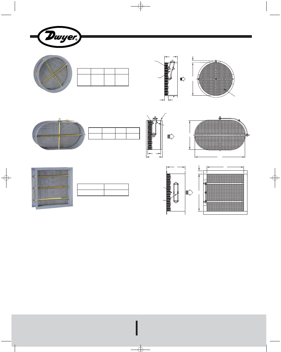
CIRCULAR FLANGE DIMENSIONS
AIR
STRAIGHTENER
[F]
[D]
AIRFLOW
TOTAL PRESSURE
(T.P.) TAKEOFF
1/4˝ COMPRESSION
FITTING
[L]
STATIC PRESSURE
(S.P.) TAKEOFF
1/4˝ COMPRESSION
FITTING
3.25
[H]
[W]
.25˝ RADIUS
BEADED EDGE (TYP)
TOTAL PRESSURE
(T.P.) TAKEOFF
1/4˝ COMPRESSION
FITTING
AIRFLOW
STATIC PRESSURE
(S.P.) TAKEOFF
1/4˝ COMPRESSION
FITTING
[L]
[L+2.5]
[W]
[F]
[H]
TOTAL PRESSURE
(T.P.) TAKEOFF
1/4˝ COMPRESSION
FITTING
STATIC PRESSURE
(S.P.) TAKEOFF
1/4˝ COMPRESSION FITTING
AIRFLOW
8˝
Station
Size “H” or “W”
8˝ – 72˝
73˝ & OVER
Flange
Size “F”
1-1/2˝
2˝
RECTANGULAR FLANGE DIMENSIONS
Station
Width “W”
Up to 44˝
Over 44˝
Flange
Thickness
.064˝
.188˝
Flange
Size
1-1/2˝
1-1/2˝
*Casing
Length “L”
8˝
10˝
OVAL FLANGE DIMENSIONS (OPTIONAL)
*NOTE: All oval flow stations without
flange have a casing length of 8˝.
SELECTABLE SIZES:
1. OVAL OR RECTANGULAR “H” OR “W” DIMENSIONS IN INCHES CAN BE THE FOLLOWING: 8, 10, 12, 14, 16, 18, 20, 22, 24, 26, 28, 30, 32, 34, 36, 40, 44, 48, 52, 56, 60, 66, 72, 78, 84, 90, 96, 102, 108, 114 or 120.
2. CIRCULAR “D” DIMENSION IN INCHES CAN BE THE FOLLOWING: 8, 10, 12, 14, 16, 18, 20, 22, 24, 26, 28, 30, 32, 36, 40, 44, 48, 54, 60, 66, 72, 78, 84, 90, 96, 102, 108, 114 or 120
F-STRA.qxd:F-FLFX.qxd 12/16/08 1:18 PM Page 1