Dwyer FAFM User Manual
Dwyer instruments, inc, Series fafm fan inlet air flow measuring probe
Bulletin AV-1-FAFM
DWYER INSTRUMENTS, INC.
Phone: 219/879-8000
www.dwyer-inst.com
P.O. BOX 373 • MICHIGAN CITY, INDIANA 46361, U.S.A.
Fax: 219/872-9057
e-mail: [email protected]
Specifications - Installation and Operating Instructions
Series FAFM Fan Inlet Air Flow Measuring Probe
The Model FAFM Fan Inlet Air Flow Measuring Probes use
evenly distributed total and static pressure measuring points to
deliver an accurate measurement of flows in a fan inlet. The Air
Flow Measuring Probes can be completely installed from outside
of the fan making it ideal for when proper duct locations are
unavailable. With its lightweight and durable construction in
addition to its ease of installation, this product lends itself to being
used in the HVAC industry.
There are two versions of the model FAFM fan inlet air flow probes
to choose from depending on the depth of the fan inlet.
For fan inlets with depth less than 3-1/2˝ (8.89 cm): Please
order a fan inlet probe with an “S” suffix. This probe has a
diameter of .375˝ (.95 cm). It employs one total flow measuring
tube and one static measuring tube. Each probe is covered with
an extruded aluminum anodized coat. Each measuring tube has
multiple sensing points.
For fan inlets with depth greater than 3-1/2˝ (8.89 cm):
Please order a fan inlet probe with a “D” suffix. This probe has a
diameter of 3-1/2˝ (8.89 cm). It employs extruded aluminum
anodized coated probes with both total and static sensors on
each tube.
SPECIFICATIONS
Wetted Materials: Aluminum with clear anodized finish.
Accuracy: ±2% (Note: Field Calibration May Be Required).
Max. Temperature: 400ºF (204ºC).
Minimum Design Flow: 400 fpm (2.03 m/sec).
Maximum Design Flow: 12,000 fpm (60.96 m/sec).
Process Connections: 1/4˝ NPT female.
INSTALLATION
When you unpack the Model FAFM Fan Inlet Air Flow
Measurement Probe ensure that there is no visible damage from
shipping. Inspect each sensing point on the probes to ensure that
they are not filled with debris from shipping. If there is obvious
shipping damage, the probe must be replaced prior to use to
avoid inaccurate measurements. Please contact Dwyer
Instruments, Inc. if it is necessary to replace your air flow
measurement probe.
Please note that Model FAFM Fan Inlet Air Flow Measurement
Probes should be installed in portion of the fan inlet with the
smallest diameter.
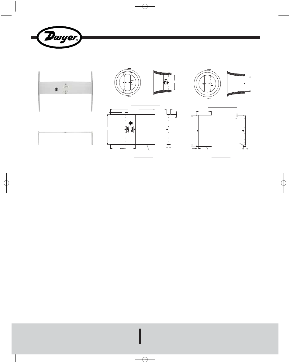
L
A
A
A
INLET FLOW VIEW
SECTION A-A
APPLICATION DIAGRAM
D
7/8
[22.23]
12
[304.80]
3-1/8
[79.38]
3-5/8
[92.20]
MOUNTING PLATES TO
BE BENT TO FIT INLET
5/16
[7.70]
1/16
[1.63]
1
[25.40]
MODEL FAFM-D
B
B
A
INLET FLOW VIEW
SECTION B-B
APPLICATION DIAGRAM
D
L
4
[101.60]
Ø3/8
[9.53]
MOUNTING PLATES TO
BE BENT TO FIT INLET
1/16
[1.98]
R3/16
[4.76]
3/4
[19.05]
MODEL FAFM-D
FAFM-D-xxxx
FAFM-S-xxxx
L = Fan Inlet Dia.
AV-1-FAFM:TEMPLATE 9/11/08 9:51 AM Page 1