Outline of installation procedure, Bulletin f-107-uxf3 – Dwyer UXF3 User Manual
Page 15
-7-
2. INSTALLATION AND BEFORE START OF
OPERATION OF THE FLOW TRANSMITTER
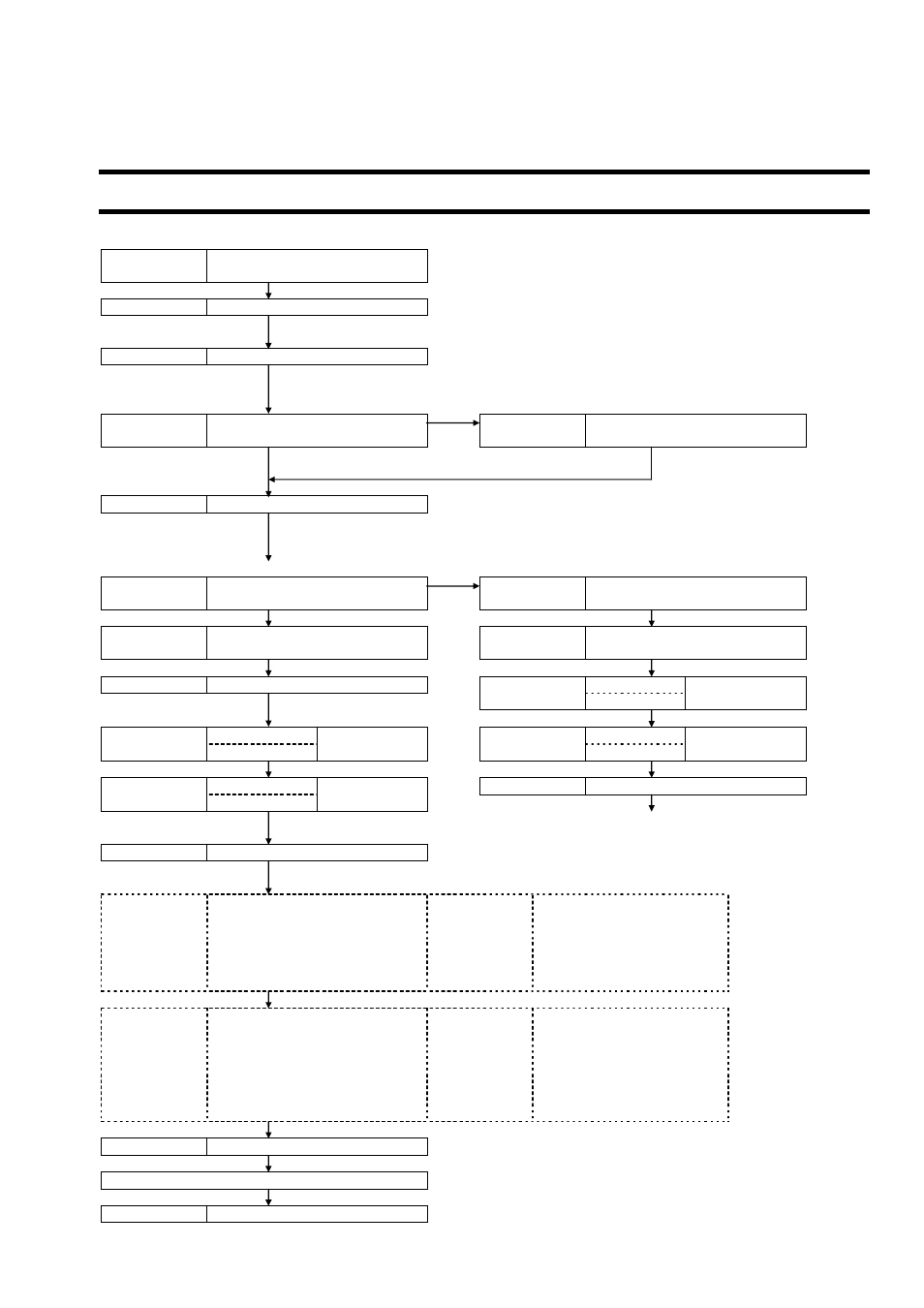
2.1. Outline of installation procedure
Section 3.3
Section 3.4
Installation of flow transmitter
Flow transmitter wiring
Power
ON
*
Check the power supply specifications and wiring before
turning on the power. (Refer to “1.2.Check on type and
specifications”.)
Section 4.4
Parameter protection
* Metric system is selected for unit.
*
The initial display language is English. Switch the languages
as required.
NG
Section 4.6
Checking and Setting of Piping
Specifications/Detector
Section 4.6.2
Piping parameter setting method
OK
Section 5
Mounting of detector
*
Be careful not to mount the sensor units with wrong mounting
dimension. Mount it with the dimension displayed at the
process setting of the piping parameter. (Refer to “5.
Mounting of detector”.)
NG (LED display is red)
Section 6.6.1.3 Checking the RAS information
Section 6.6.2
Displaying the data in
maintenance mode
OK
(LED display is green)
Section 6.6.2
Displaying the data in
maintenance mode
Check the data display
Check the data display
AGC U
AGC
D
35% or more
AGC U
P/H U
AGC
D
35% or more
P/H
D
Outside the range
of 5528 to 6758
P/H U
Section 6.6.6
Checking received waveforms
P/H
D
5528 to 6758
Contact manufacturer's service representative.
Section 4.7
Zero Adjustment
*
Before performing zero point adjustment, check that the pipe
is filled with fluid, the fluid is in still state, and that the
measurement status is normal.
Basic operation
Section 4.9.1.3 Output limit
Section 4.8.1
How to set the unit system
Section 4.9.2
Setting the total
Section 4.9.3
Setting the DO output
Section 4.9.1.1 Setting of flow rate range (single
range)
Section 4.9.3.1 How to validate the total pulse
output
Section 4.9.1.2 Setting of analog output at error
(Burnout)
Section 4.9.4
Setting the LCD indication
Application
operation
Section 4.9.1
Setting of flow rate range
Section 4.10.1 Setting automatic 2 ranges
Section 4.10.5.2 How to validate the alarm
output
Section 4.10.2 Setting the Bi-directional range
Section 4.10.5.3 Setting the flow switch
Section 4.10.3 Setting the Bi-directional auto 2
range
Section 4.10.5.4 How to validate the total
switch
Section 4.10.6
Setting the DI input
Section 7.3
ORDERING INFORMATION
Run
(Measurement)
Section
6 CHECK
AND
MAINTENANCE
Bulletin F-107-UXF3