Intermec 6710 User Manual
Page 69
SECTION 4
"
Configuration
6710 Access Point User’s Guide 4-3
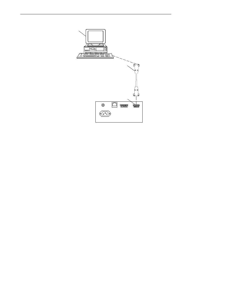
1. PC with terminal emulation program
2. Cable: 321-355-001 for a 25-pin PC COM port
or
Cable: 226-106-001 for a 9-pin PC COM port
(standard null modem cable)
3. 6710 Access Point DIAG port
2
Figure 4-1
Local Session
3
10BASE2
10BASET
AC INPUT
AUI
DIAG
100/240 VAC
1
1. Ensure the terminal emulation program is installed
on the PC.
2. With both the PC and access point powered OFF,
connect the communication cable to the appropriate
PC COM port.