Yaskawa FSP Amplifier User Manual
Page 97
FSP Amplifier User’s Manual
Chapter 5: Parameter Settings and Functions
5-30
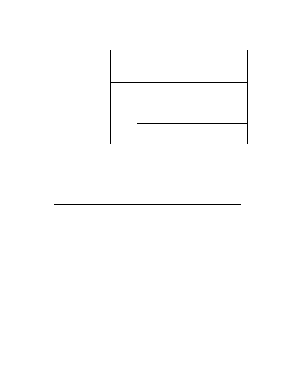
Meanings for the following signals change when the contact input
speed control function is used:
Pn000.1
Setting
Description
Input Signal
/P-CON (CN1-41)
Used to switch between P and PI
control.
/P-CL (CN1-45)
Used to switch between forward
external torque limit ON and OFF.
0, 2, 8, 9, A,
B, C
Input
contacts.
Speed control
function is not
used.
/N-CL (CN1-46)
Used to switch between reverse
external torque limit ON and OFF.
/P-CON
(/SPD-D)
/P-CL
(/SPD-A)
/N-CL
(/SPD-B)
Speed
setting
0 0
0 reference
etc.
0 1
SPEED 1
(Pn301)
1 1
SPEED 2
(Pn302)
3, 4, 6
Input
contacts.
Speed control
function is
used.
Direction
of rotation
0:
Forward
1:
Reverse
1 0
SPEED 3
(Pn303)
Note: 1.
0: OFF (high level); 1: ON (low level)
2.
/P-CON, /P-CL and /N-CL functions differ from those in the table above when Pn000.1 is set to 3, 4, or 6.
The function is switched automatically when Pn50A. 0 is set to 0.
3.
The /SPD-D, /SPD-A, and /SPD-B signals can be used only when signals are allocated to the input
circuits. See
5.3.3 Input Circuit Signal Allocation.
2. Set the motor speeds using the following parameters.
Parameter
Signal
Setting (rpm)
Control Mode
Pn301
Speed 1 (SPEED 1)
(Contact Input Speed
Control)
Range: 0 to 10000
Default Setting: 100
Speed Control
Pn302
Speed 2 (SPEED 2)
(Contact Input Speed
Control)
Range: 0 to 10000
Default Setting: 200
Speed Control
Pn303
Speed 2 (SPEED 2)
(Contact Input Speed
Control)
Range: 0 to 10000
Default Setting: 300
Speed Control
These parameters are used to set motor speeds when the contact input
speed control function is selected. If the setting is higher than the
maximum motor speed of the servomotor, then the servomotor will
rotate at its maximum speed.
Speed selection input signals /P-CL(SPD-A)(CN1-45) and /N-CL
(/SPD-B) (CN1-46) and the rotation direction selection signal /P-CON
(/SPD-D)(CN1-41) enable the servomotor to run at the preset speeds.