Yaskawa FSP Amplifier User Manual
Page 73
FSP Amplifier User’s Manual
Chapter 5: Parameter Settings and Functions
5-6
Servomotor Stop Mode for P-OT and N-OT Input Signals
Set the following parameters to specify the servomotor Stop mode when P-
OT and N-OT input signals are used.
Specify the servomotor Stop mode when either of the following signals is
input during servomotor operation.
• Forward run prohibited input (P-OT, CN1-42)
• Reverse run prohibited input (N-OT, CN1-43)
• Set the parameters according to limit switch type (NO or NC)
Parameter Signal
Setting
Description
Example: 2
Uses the P-OT input signal to prevent
forward rotation. (Forward rotation is
prohibited when CN1-42 is open and is
allowed when CN1-42 is at 0 V).
Default Setting: 8
Does not use the P-OT input signal to
prevent forward rotation. (Forward
rotation is always allowed and has the
same effect as shorting CN1-42 to 0 V).
Pn50A.3
P-OT Signal
Mapping
(Forward Run
Prohibit Input
Signal)
Example: B
Inputs the reverse signal from CN1-42
input terminal.
For more options of parameters Pn50A.3 and Pn50B.0 refer to Appendix D.3. Input Signal
Selections
Example: 3
Uses the N-OT input signal to prevent
reverse rotation. (Reverse rotation is
prohibited when CN1-43 is open and is
allowed when CN1-43 is at 0 V).
Default Setting: 8
Does not use the N-OT input signal to
prevent reverse rotation. (Reverse
rotation is always allowed and has the
same effect as shorting CN1-43 to 0 V).
Pn50B.0
N-OT Signal
Mapping
(Reverse Run
Prohibit Input
Signal)
Example: C
Inputs the reverse signal from CN1-43
input terminal.
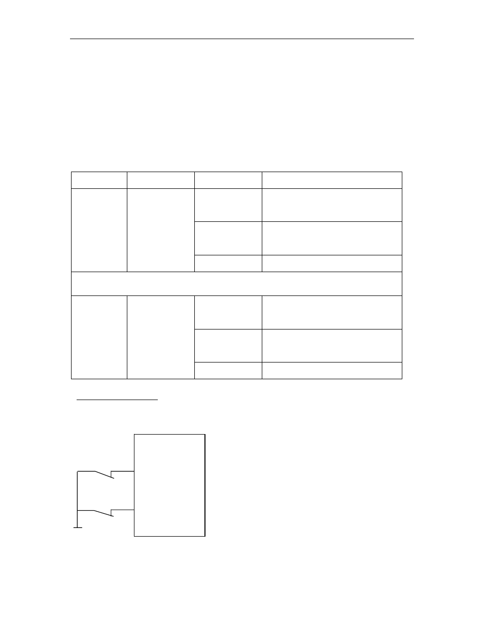
Connection example:
Normally Closed type
P-OT
N-OT
COM of 24 V
FSP Amplifier
CN1-42
CN1-43