Yaskawa FSP Amplifier User Manual
Page 350
FSP Amplifier User’s Manual
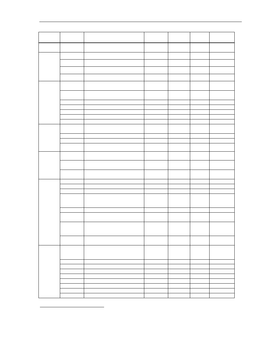
Appendix D: List of Parameters
D-5
Speed
Parameter
Pn308
Speed Feedback Filter Time
Constant
0.01 ms
0-65535
0
—
Pn380
Speed1
mm / s
0-5000
10
—
Pn381
Speed2
mm / s
0-5000
20
—
Pn382
Speed3
mm / s
0-5000
30
—
Linear
Mo
tor
Speed
Param
eters
Pn383
Jog Speed
mm / s
0-5000
50
—
Pn400
Torque Reference Input Gain
0.1 V / rated
torque
10-100 30 5.2.7
Pn401
Torque Reference Filter Time
Constant
0.01 ms
0-65535
100
6.2.2
Pn402
Forward Torque Limit
%
0-800
800
5.1.3
Pn403 Reverse
Torque
Limit
% 0-800 800 5.1.3
Pn404
Forward External Torque Limit
%
0-800
100
5.1.3
Pn405
Reverse External Torque Limit
%
0-800
100
5.1.3
Torque
Para
meter
s
Pn406
Emergency Stop Torque
%
0-800
800
5.1.2
Pn407
Speed Limit during Torque
Control
rpm 0-10000
10000 5.2.7
Pn408
Torque Function Switches
—
—
0000
6.2.9
Pn409
Notch Filter Frequency
Hz
50-2000
2000
6.2.9
Torque
Param
eters
Pn40A
Notch Filter width
Hz
70-1000
70
6.2.9
Pn480
Speed limit during torque control
mm / s
0-5000
5000
—
Pn483 Forward
force
limit
% of rated
force
0-800 10
—
Linear
Mo
tor
Torque
Param
eters
Pn484 Reverse
force
limit
% of rated
force
0-800 10
—
Pn500
Positioning Completed Width
ref. units
0-250
7
5.5.3
Pn501 Zero
Clamp
Level
rpm 0-10000 10 5.4.3
Pn502
Rotation Detection Level
rpm
1-10000
20
5.5.5
Pn503
Speed Coincidence Signal
Output
Width
rpm 0-100 10 5.5.4
Pn504
NEAR Signal Width
ref. units
1-250
7
5.5.8
Pn505 Overflow
Level
256 ref.
units
1-32767 1024
6.2.1
Pn506
Brake Reference Servo OFF
Delay
Time
10ms 0-50 0 5.4.4
Sequen
ce P
a
ram
e
ter
s
Pn507
Brake Reference Output Speed
Level
rpm 0-10000
100 5.4.4
Pn508
Timing for Brake Reference
Output
during Motor Operation
10 ms
10-100
50
5.4.4
Pn509
Momentary Hold Time
ms
20-1000
20
5.5.9
Pn50A*
Input Signal Selections 1
—
—
2100
5.3.3
Pn50B*
Input Signal Selections 2
—
—
6543
5.3.3
Pn50C*
Input Signal Selections 3
—
—
8888
5.3.3
Pn50D*
Input Signal Selections 4
—
—
8888
5.3.3
Pn50E*
Output Signal Selections 1
—
—
3211
5.3.4
Pn50F*
Output Signal Selections 2
—
—
0000
5.3.4
Sequen
ce P
a
ram
e
ter
s
Pn510*
Output Signal Selections 3
—
—
0000
5.3.4
*
After changing this parameter, cycle the main circuit and control power supplies to enable the new settings.
Category
Parameter
Number
Name
Unit
Setting
Range
Default
Setting
Reference