Yaskawa FSP Amplifier User Manual
Page 63
FSP Amplifier User’s Manual
Chapter 4: Trial Operation
4-8
Operating Procedure In Position Control Mode:
Set Pn000.1 to C
1. Set the parameter Pn200.0 so that the reference pulse form is the same
as the host controller output form.
To select the reference pulse form, see 5.2.2 Position Reference.
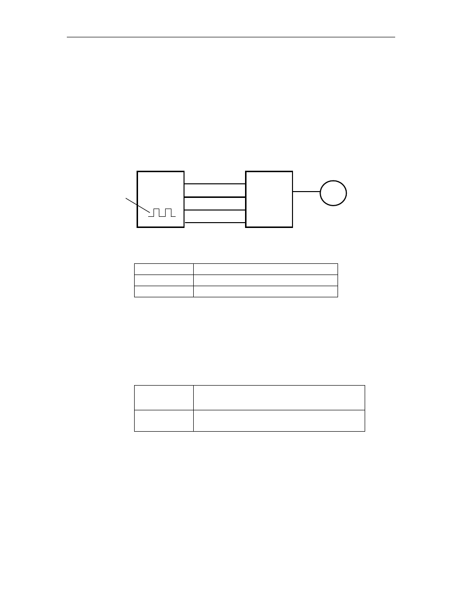
2. Input a slow speed pulse from the host controller and execute low-
speed operation.
Host controller
FSP Amplifier
Reference
pulse
Servomotor
PULS
/PULS
/SIGN
SIGN
CN1-7
CN1-8
CN1-11
CN1-12
3. Check the following data in Monitor mode. See 7.1.6 Operation in
Monitor Mode.
Un000 Actual
motor
speed
Un007
Reference pulse speed display
Un008 Position
offset
• Has the reference pulse been input?
• Is the motor speed as defined?
• Does the reference speed coincide with the actual motor speed?
• Does the servomotor stop when the speed reference is 0?
4. Reset the parameters shown below to change the motor speed or
direction of rotation.
Pn202, Pn203
Electronic gear ratio
See 5.2.5 Using the Electronic Gear Function.
Pn000.0
Selects the direction of rotation.
See 5.1.1 Switching Servomotor Rotation Direction.
If an alarm occurs or the servomotor fails to operate during the above
operation, the CN1 connector wiring is incorrect or the parameter
settings do not match the host controller specifications. Check the
wiring and review the parameter settings, then repeat step 1.
Note: References
• List of alarms: See 9.2.3 Alarm Display Table.
• List of parameters: See Appendix D, List of Parameters.