D-10 – Yaskawa FSP Amplifier User Manual
Page 355
FSP Amplifier User’s Manual
Appendix D: List of Parameters
D-10
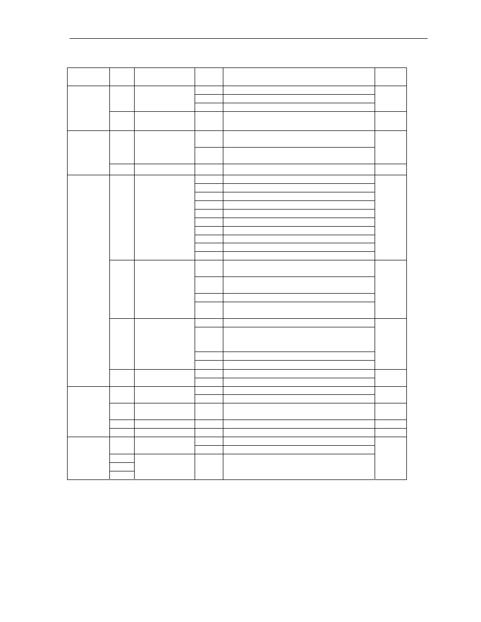
0 Not
defined
1 U
V
W
0
Motor phase
order
2 U
W
V
0
Pn191
Motor
sele
cti
o
n
Switc
h
es
1-3
Not used
—
—
—
0
Disable clear integral function
(refer to 6.3.7)
0 Integral
mode
1
Enable clear integral function
(refer to 6.3.7)
1
Pn1A7
Motor
sele
cti
on
Switc
h
es
1-3
Not used
—
—
—
0
Sign + pulse, positive logic.
1
CW + CCW, positive logic.
2
A phase + B phase (x1), positive logic.
3
A phase + B phase (x2), positive logic.
4
A phase + B phase (x4), positive logic.
5
Sign + pulse, negative logic.
6
CW + CCW, negative logic.
7
A phase + B phase (x1), negative logic.
8
A phase + B phase (x2), negative logic.
0
Reference
Pulse Form
9
A phase + B phase (x4), negative logic.
0
0
Clears error counter when the signal goes
high.
1
Clears error counter at the rising edge of the
signal.
2
Clears error counter when the signal goes low.
1
Error Counter
Clear Signal
Form
3
Clears error counter at the falling edge of the
signal.
0
0
Clears error counter at the base block.
1
Does not clear error counter. (Possible to clear
error
counter only with CLR signal).
2
Clears error counter when an alarm occurs.
2
Clear
Operation
3
Clear signal ignore
0
0
Reference input filter for line driver signals.
Pn200
Posit
ion C
ontro
l R
efer
enc
es S
elec
tion
Sw
itc
hes
3 Filter
Selection
1
Reference input filter for open collector signals.
0
0
Doesn’t use check sum
0 Check
Sum
1
Use check sum
1
1
Communication
definitions
0
Default comm. setting (1 Start, 7 data, Even-
parity)
0
2 Not
used
—
—
—
Pn2C
6
C
o
mmu
ni
cati
on Sw
itch
3 Not
used
—
—
—
0 Disabled.
0
Notch Filter
Selection
1
Uses a notch filter for torque reference.
1
2
Pn408
Torque
C
ontrol
Funct
ion
Switc
h
es
3
Not used.
—
—
0
Parameter
Digit
Place
Name
Setting
Description
Default
Setting