D.1. parameters – Yaskawa FSP Amplifier User Manual
Page 347
FSP Amplifier User’s Manual
Appendix D: List of Parameters
D-2
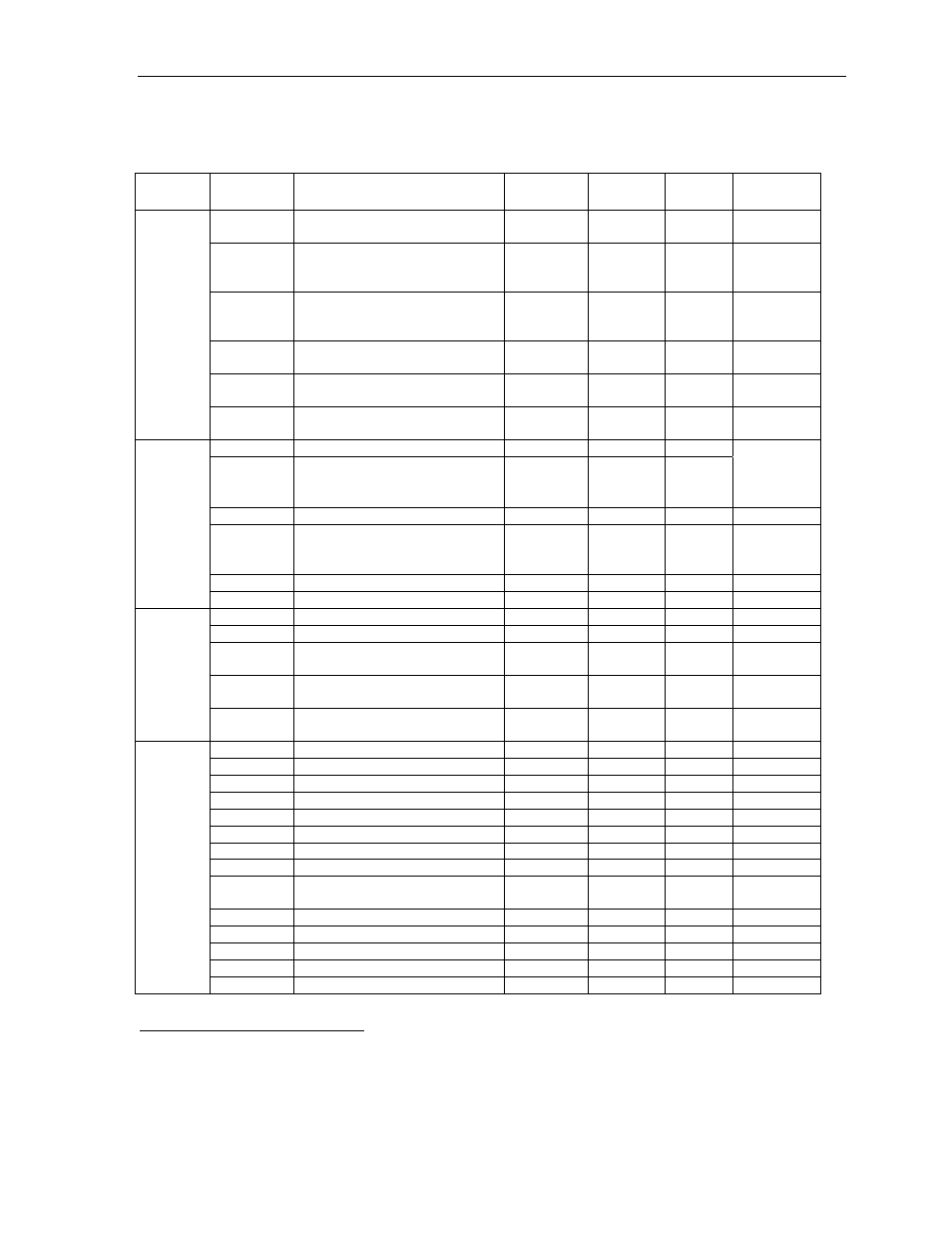
D.1. Parameters
The following list shows parameters and their settings.
Category
Parameter
Number
Name
Unit
Setting
Range
Default
Setting
Reference
Pn000*
Function Selection Basic
Switches
— —
0x00D0
5.1.1,
5.3.5
Pn001*
Function Selection Application
Switches 1**
— —
0000
5.1.2,
5.4.2,
5.5.7
Pn002*
Function Selection Application
Switches
— —
0000
5.2.8,
5.2.9,
5.7.2
Pn003
Function Selection Application
Switches 3
— —
0002
6.4
Pn006
Function Selection Application
Switches 3
— —
0000
6.4
Funct
ion S
ele
cti
on Par
ame
ter
s
Pn007
Function Selection Application
Switches 3
— —
0000
6.4
Pn100 Speed
Loop
Gain
Hz 1-2000 40
Pn101
Speed Loop Integral Time
Constant
0.01 ms
15-51200
2000
6.2.2,
6.2.7,
6.2.10
Pn102 Position
Loop
Gain
s
-1
1-2000 40 6.2.10
Pn103 Inertia
Ratio
% 0-10000 0
6.2.6,
6.3.1,
6.3.4
Pn109 Feed-Forward
(Speed
control) % 0-100 0 6.2.2
Gain Para
m
e
te
rs
Pn110*
Online Autotuning Switches
—
—
0010
—
Pn190*
Motor selection switch
—
—
0000
5.8
Pn191*
Motor selection switch
—
—
0000
5.8
Pn192*
Pulses number of A quad B
encoder (Low)
Pulses/rev 0-9999 2048
5.8
Pn193*
Pulses number of A quad B
encoder (High)
Pulse *
10000 / Rev
0-419 0 5.8
Motor para
m
et
ers
Pn199*
Encoder counts per Scale Pitch
of linear motor
Counts /
Scale Pitch
1-256 1
—
Pn1A0
Global gain factor (Tightness)
%
0-500
60
6.3.3
Pn1A2
Speed feedback filter 0.01
ms
30-3200
40
6.3.4
Pn1A4
Torque filter (low pass) 0.01
ms
0-2500
20
6.3.4
Pn1A5
Torque filter (second order)
0.1%
0-1000
0
6.3.4
Pn1A7 Integral
mode
switch
—
— 1121 6.3.7
Pn1A9
Integral feedback gain
Hz
0-500
40
6.3.4
Pn1AA Proportional
feedback
gain
Hz 0-500 40 6.3.3
Pn1AB
Supplementary proportional
feedback gain
Hz 0-500 30 6.3.3
Pn1AC
Speed feedback gain
Hz
0-2000
80
6.3.3
Pn1AF
Feed forward gain
%
0-200
0
6.3.3
Pn1B5
Maximum variable gain
%
100-1000
160
6.3.6
Pn1BB
Feed forward compensation
Hz
10-2000
2000
—
G
ain par
ame
ters
Pn1BC
Filter on command acceleration
0.01 ms
0-2500
300
—
* After changing this parameter, cycle the main circuit and control power supplies to enable the new settings.
** The multi-turn limit is valid only when parameter Pn002.2 Absolute Encoder Usage is set to "2". The value will be
processed in the range of "+32767 to -32768" for other settings even if the value is changed. There is no need to change the
multi-turn limit except for in special cases. Be careful not to change the setting unless necessary.