Input circuit example – Yaskawa FSP Amplifier User Manual
Page 80
FSP Amplifier User’s Manual
Chapter 5: Parameter Settings and Functions
5-13
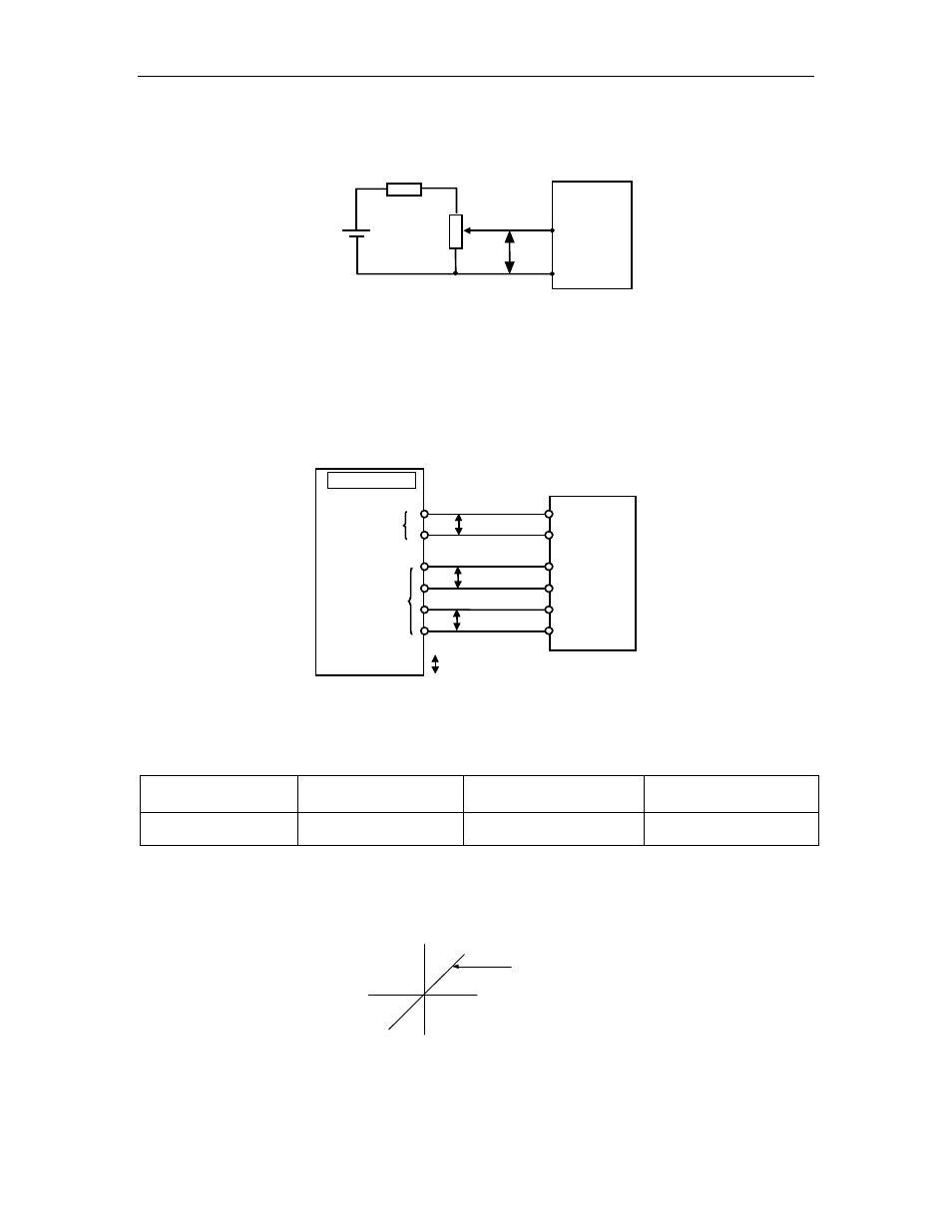
Input Circuit Example
P
V-REF
2 kΩ
470 Ω, 1/2 W min.
+ 12 V
SG
CN1-5
CN1-6
FSP Amplifier
Always use twisted pair cable for noise control.
Recommended variable resistor: Model 25HP-10B manufactured by Sakae
Tsushin Kogyo Co., Ltd.
Connect V-REF and SG to the speed reference output terminals on the host
controller when using a host controller, such as a programmable controller,
for position control.
CN1-5
CN1-6
FSP Amplifier
CN1-33
CN1-34
CN1-35
CN1-36
V-REF
SG
P
PAO
/PAO
PBO
/PBO
P
P
Speed
reference
output
terminals
Feedback
pulse input
terminals
Host controller
P: Indicates twisted-pair
Adjust Pn300 according to the output voltage specifications of the host
controller.
Adjust the speed reference input adjustment factor in the following
parameter.
Parameter
Signal
Setting (0.01 V / Rated
Motor Speed)
Control Mode
Pn300
Speed Reference Input
Adjustment Factor
Range:
150 to 3000
Speed Control and
Programming
Set the voltage range for the V-REF speed reference input at CN1-5
according to the host controller and external circuit output range.
Set this slope
Reference
speed (rpm)
Reference
voltage (V)
The default setting is adjusted so that a 6 V input is equivalent to the rated
motor speed of all applicable servomotors.
Note: The maximum allowable voltage to the speed reference input (between CN1-5 and 6) is ± 12 VDC.