Yaskawa FSP Amplifier User Manual
Page 133
FSP Amplifier User’s Manual
Chapter 5: Parameter Settings and Functions
5-66
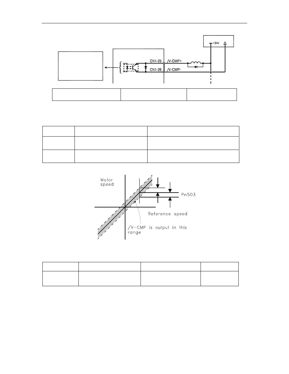
(per output)
0V
Photocoupler output
Maximum operating
voltage: 30 VDC
50mA DC
Maximum output current:
I/ O power supply
XtraDrive
FSP Amplifier
Output Ö /V-CMP CN1-25
Speed Coincidence Output
Signal
Speed Control
This signal is output when the actual motor speed during speed control is
the same as the speed reference input.
/V-CMP State
Status
Result
ON
Circuit between CN1-25 and 26 is
closed, and CN1-25 is at low level.
Speed coincides. (Speed error is below the
setting.)
OFF
Circuit between CN1-25 and 26 is
open, and CN1-25 is at high level.
Speed does not coincide. (Speed error is
above the setting.)
The following parameter setting is used to change the CN1 connector
terminal that outputs the /V-CMP signal.
Parameter Signal
Setting
Control Mode
Pn50E
Output Signal Selections 1
Default Setting: 3211
Speed, Torque,
Position Control,
and Programming
The parameter is default set so the /V-CMP signal is output between CN1-
25 and 26. See 5.3.4 Output Circuit Signal Allocation for more details on
parameter Pn50E.
The following parameter is used to set conditions for speed coincidence
output.