Mpls te configuration examples, Mpls te using static cr-lsp configuration example, Network requirements – H3C Technologies H3C SR8800 User Manual
Page 98: Configuration procedure
87
Task
Command
Remarks
Display information about the
specified tunnels and their
protection tunnels.
display mpls te protection tunnel { tunnel-id |
all } [ verbose ] [ | { begin | exclude | include }
regular-expression ]
Available in any view
Display information about DS-TE.
display mpls te ds-te [ | { begin | exclude |
include } regular-expression ]
Available in any view
Clear the statistics about RSVP-TE.
reset mpls rsvp-te statistics { global | interface
[ interface-type interface-number ]
Available in user view
MPLS TE configuration examples
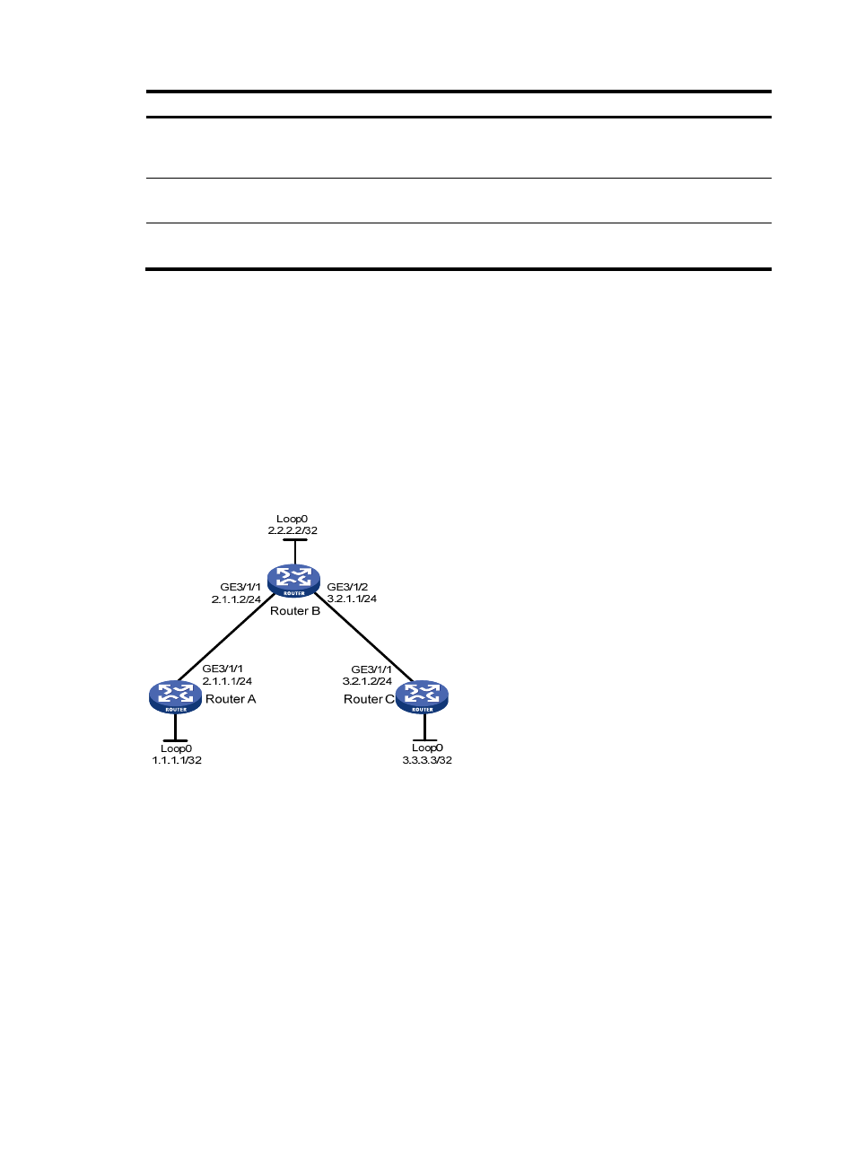
MPLS TE using static CR-LSP configuration example
Network requirements
Router A, Router B, and Router C run IS-IS.
Establish a TE tunnel using a static CR-LSP between Router A and Router C.
Figure 24 Network diagram
Configuration procedure
1.
Assign IP addresses and masks to interfaces (see
). (Details not shown)
2.
Enable IS-IS to advertise host routes with LSR IDs as destinations
# Configure Router A.
[RouterA] isis 1
[RouterA-isis-1] network-entity 00.0005.0000.0000.0001.00
[RouterA-isis-1] quit
[RouterA] interface GigabitEthernet 3/1/1
[RouterA-GigabitEthernet3/1/1] isis enable 1
[RouterA-GigabitEthernet3/1/1] quit
[RouterA] interface loopback 0