Network requirements – H3C Technologies H3C SR8800 User Manual
Page 118
107
Details not shown
5.
Configure the MPLS TE tunnel
Details not shown
6.
Configure RSVP-TE GR
# Configure Router A.
[RouterA] mpls
[RouterA-mpls] mpls rsvp-te graceful-restart
# Configure Router B.
[RouterB] mpls
[RouterB-mpls] mpls rsvp-te graceful-restart
# Configure Router C.
[RouterC] mpls
[RouterC-mpls] mpls rsvp-te graceful-restart
7.
Verify the configuration
After previous configurations, a tunnel is created between Router A and Router C. Issuing the
following command, you will see that the neighbor’s GR status is Ready.
Interface GigabitEthernet3/1/1
Neighbor Addr: 10.1.1.2
SrcInstance: 880 NbrSrcInstance: 5017
PSB Count: 0 RSB Count: 1
Hello Type Sent: REQ Neighbor Hello Extension: ENABLE
SRefresh Enable: NO
Graceful Restart State: Ready
Restart Time: 120 Sec Recovery Time: 300 Sec
MPLS RSVP-TE and BFD cooperation configuration example
Network requirements
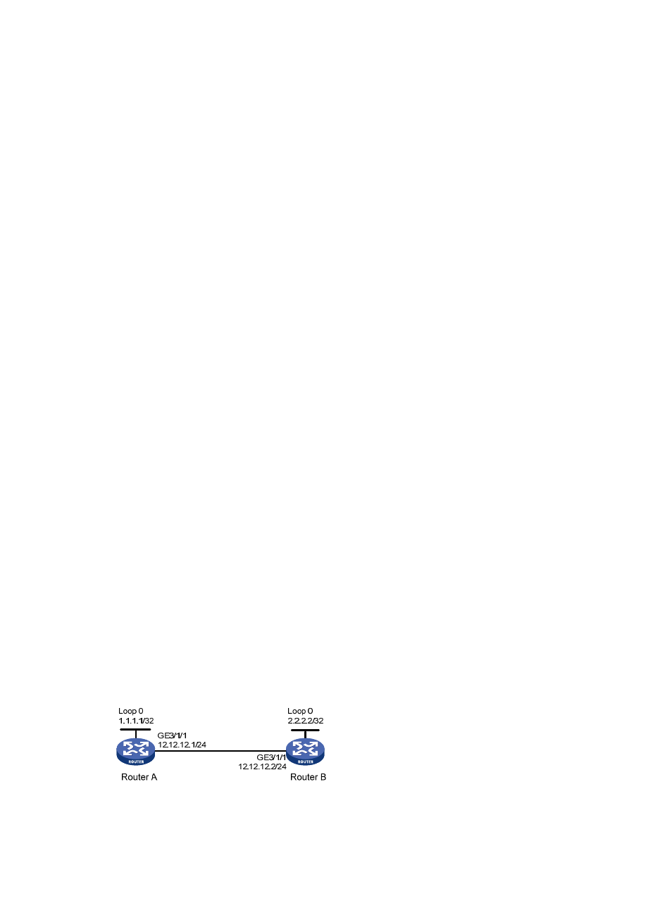
Router A and Router B are connected directly. Enable MPLS RSVP-TE BFD on the interfaces connecting the
two routers, and run OSPF on the routers to ensure reachability at the network layer.
If the physical link between Router A and Router B fails, BFD can detect the failure quickly and inform
MPLS RSVP-TE of the failure.
Figure 28 Network diagram