Vpls configuration task list – H3C Technologies H3C SR8800 User Manual
Page 172
161
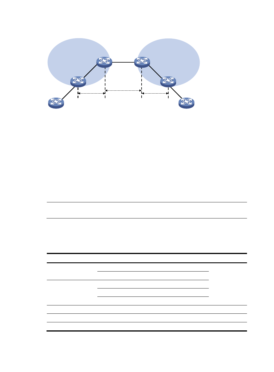
Figure 41 Diagram for multi-hop PW
As shown in
, PE 1 and PE 2 are in different ASs. To set up a multi-hop PW between PE 1 and
PE 2, you need to:
•
Establish three PWs: PW 1 between PE 1 and ASBR 1, PW 2 between ASBR 1 and ASBR 2, and
PW 3 between ASBR 2 between PE 2.
•
Associate PW 1 and PW 2 on ASBR 1. Then, when receiving a packet from PW 1 (or PW 2), ASBR
1 removes the existing inner and outer labels of the packet and adds the inner and outer labels of
PW 2 (or PW 1) to the packet.
•
Associate PW 2 and PW 3 on ASBR 2. Then, upon receiving a packet from PW 2 (or PW 3), ASBR
2 removes the existing inner and outer labels of the packet and then adds the inner and outer labels
of PW 3 (or PW 2) to the packet.
Thus, PW 1, PW 2, and PW 3 are put end to end and a multi-hop PW is formed across the ASs.
NOTE:
Only LDP VPLS connections can form a multi-hop PW.
VPLS configuration task list
Complete the following tasks to configure VPLS:
Task Remarks
Required
Configure either
type of VPLS as
needed
Configuring an LDP VPLS instance
Required
Required
Required
Configuring a BGP VPLS instance
Required
Required
Configuring MAC address learning
Optional
Optional
CE 1
PE 1
PE 2
ASBR 1
ASBR 2
PW 1
PW 3
CE 2
PW 2
AS 100
AS 200
MPLS backbone
MPLS backbone