Network requirements, Configuration procedure – H3C Technologies H3C SR8800 User Manual
Page 230
219
Issue the display mpls l2vpn connection command on the PEs. The output shows that an L2VPN
connection is established between the PEs and the connection is up. Take PE 1 as an example:
[PE1] display mpls l2vpn connection
1 total connections,
connections: 1 up, 0 down, 0 local, 1 remote, 0 unknown
VPN name: vpn1,
1 total connections,
connections: 1 up, 0 down, 0 local, 1 remote, 0 unknown
CE name: ce1, id: 1,
Rid type status peer-id route-distinguisher intf
2 rmt up 3.3.3.9 100:1 GigabitEthernet4/1/2
# Ping CE 2 from CE 1. The output shows that CE 1 and CE 2 can ping each other.
[CE1] ping 30.1.1.2
PING 30.1.1.2: 56 data bytes, press CTRL_C to break
Reply from 30.1.1.2: bytes=56 Sequence=1 ttl=255 time=90 ms
Reply from 30.1.1.2: bytes=56 Sequence=2 ttl=255 time=77 ms
Reply from 30.1.1.2: bytes=56 Sequence=3 ttl=255 time=34 ms
Reply from 30.1.1.2: bytes=56 Sequence=4 ttl=255 time=46 ms
Reply from 30.1.1.2: bytes=56 Sequence=5 ttl=255 time=94 ms
--- 30.1.1.2 ping statistics ---
5 packet(s) transmitted
5 packet(s) received
0.00% packet loss
round-trip min/avg/max = 34/68/94 ms
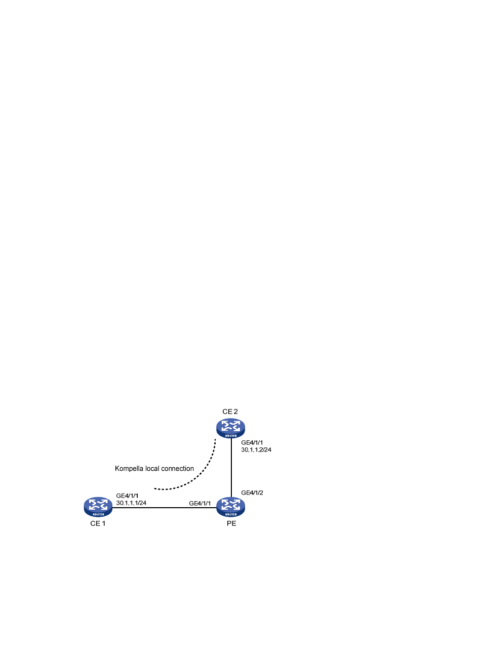
Example for configuring a Kompella local connection
Network requirements
As shown in
, create a Kompella local connection between CE 1 and CE 2.
Figure 54 Network diagram
Configuration procedure
1.
Configure the PE.
# Configure basic MPLS. (Details not shown)
# Configure the L2VPN and the CE connection.