Configuring pw redundancy for h-vpls access, Network requirements, Configuration procedure – H3C Technologies H3C SR8800 User Manual
Page 190
179
[Hub-PE-vsi-aaa-ldp] quit
[Hub-PE-vsi-aaa] quit
# Configure interface GigabitEthernet 3/1/3, bind VPLS instance aaa to the interface, and
specifying the attached CE as the hub-CE.
[Hub-PE] interface GigabitEthernet 3/1/3
[Hub-PE-GigabitEthernet3/1/3] l2 binding vsi aaa hub
[Hub-PE-GigabitEthernet3/1/3] quit
After completing previous configurations, issue the display vpls connection command on the PEs. You will
see that a PW connection in up state has been established.
Configuring PW redundancy for H-VPLS access
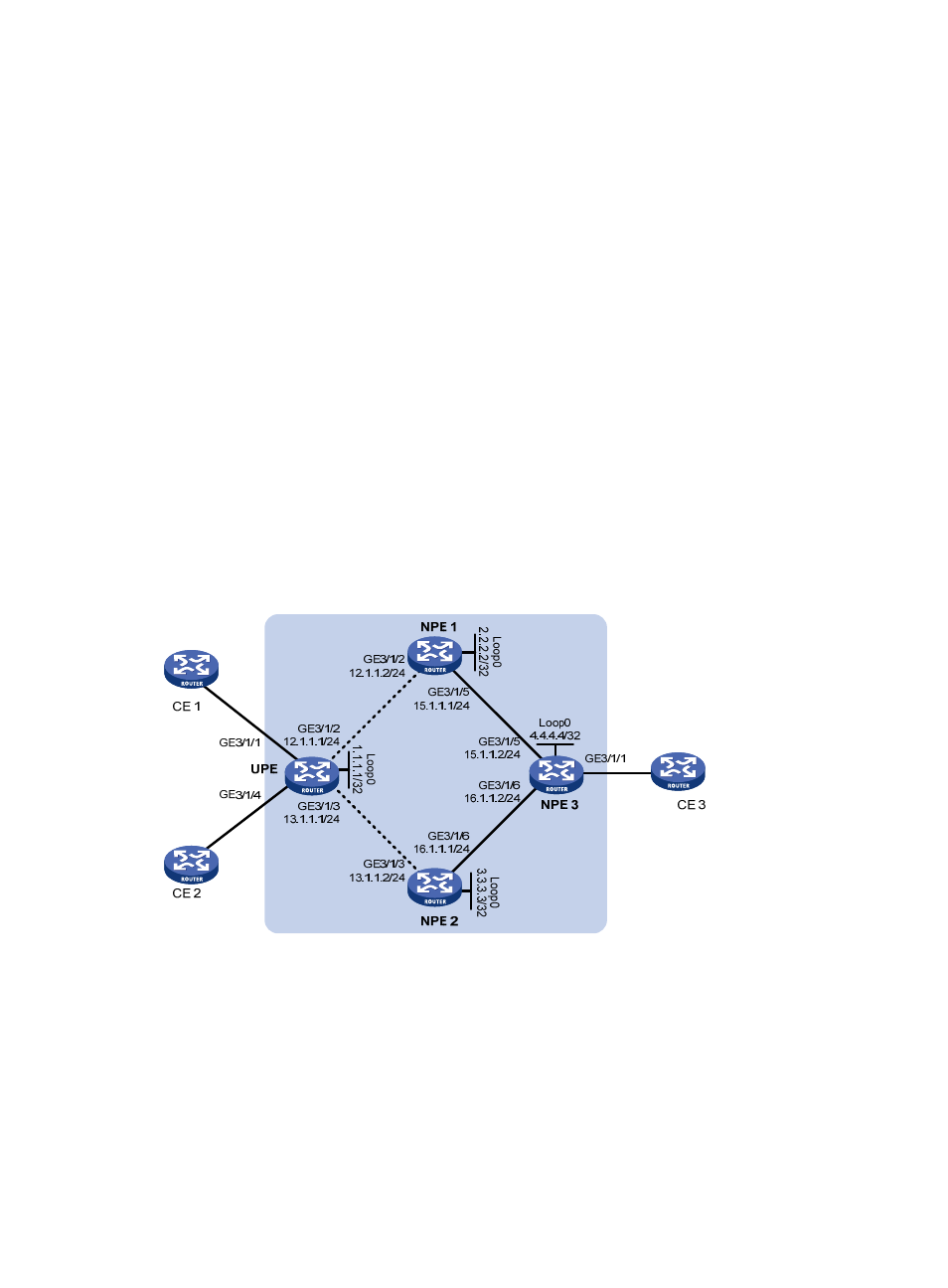
Network requirements
As shown in
, UPE establishes a PW connection (U-PW) with NPE 1 and NPE 2, with the NPE
2 link as the backup. NPE 1 and NPE 2 each establish a PW connection (N-PW) with NPE 3. CE 3 is
connected to the network through NPE 3.
UPE is connected to NPE 1 through GigabitEthernet 3/1/2 and is connected to NPE 2 through
GigabitEthernet 3/1/3. NPE 1 is connected to NPE 3 through GigabitEthernet 3/1/5, and NPE 2 is
connected to NPE 3 through GigabitEthernet 3/1/6.
Configure a VPLS instance and configure it to support H-VPLS networking.
Figure 45 Network diagram
Configuration procedure
1.
Configure the IGP protocol (such as OSPF) on the MPLS backbone. (Details not shown)
2.
Configure UPE.
# Configure basic MPLS.
[Sysname] sysname UPE
[UPE] interface loopback 0
[UPE-LoopBack0] ip address 1.1.1.1 32
[UPE-LoopBack0] quit