Example for configuring martini mpls l2vpn, Network requirements, Configuration procedure – H3C Technologies H3C SR8800 User Manual
Page 224
213
5 packet(s) transmitted
5 packet(s) received
0.00% packet loss
round-trip min/avg/max = 80/126/150 ms
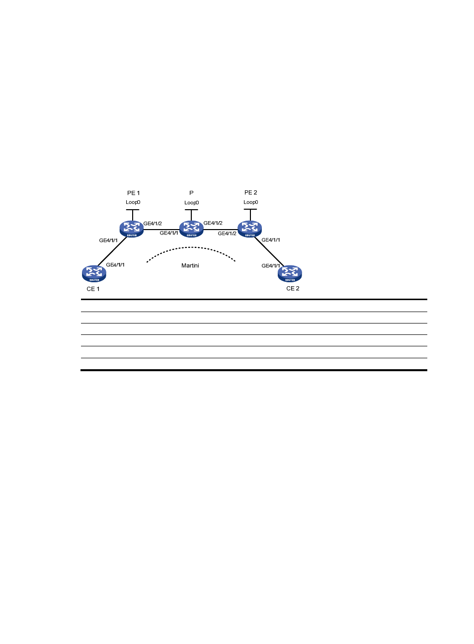
Example for configuring Martini MPLS L2VPN
Network requirements
As shown in
, the CEs are connected to PEs through GigabitEthernet interfaces.
Establish a Martini MPLS L2VPN between CE 1 and CE 2.
Figure 52 Network diagram
Device Interface IP
address
Device Interface IP
address
CE 1
GE4/1/1
100.1.1.1/24
P
Loop0
192.4.4.4/32
PE 1
Loop0
192.2.2.2/32
GE4/1/1 10.1.1.2/24
GE4/1/2 10.1.1.1/24
GE4/1/2 10.2.2.2/24
CE 2
GE4/1/1
100.1.1.2/24
PE 2
Loop0
192.3.3.3/32
GE4/1/2 10.2.2.1/24
Configuration procedure
1.
Configure CE 1.
[Sysname] sysname CE1
[CE1] interface GigabitEthernet4/1/1
[CE1-GigabitEthernet4/1/1] ip address 100.1.1.1 24
2.
Configure PE 1.
# Configure the LSR ID and enable MPLS globally.
[Sysname] sysname PE1
[PE1] interface loopback 0
[PE1-LoopBack0] ip address 192.2.2.2 32
[PE1-LoopBack0] quit
[PE1] mpls lsr-id 192.2.2.2
[PE1] mpls
# Configure the LSP establishment triggering policy.
[PE1-mpls] lsp-trigger all
[PE1-mpls] quit