Mpls te in mpls l3vpn configuration example, Network requirements, Configuration procedure – H3C Technologies H3C SR8800 User Manual
Page 154
143
Outgoing Tunnel ID : 0x15000d
Label Operation : SWAP
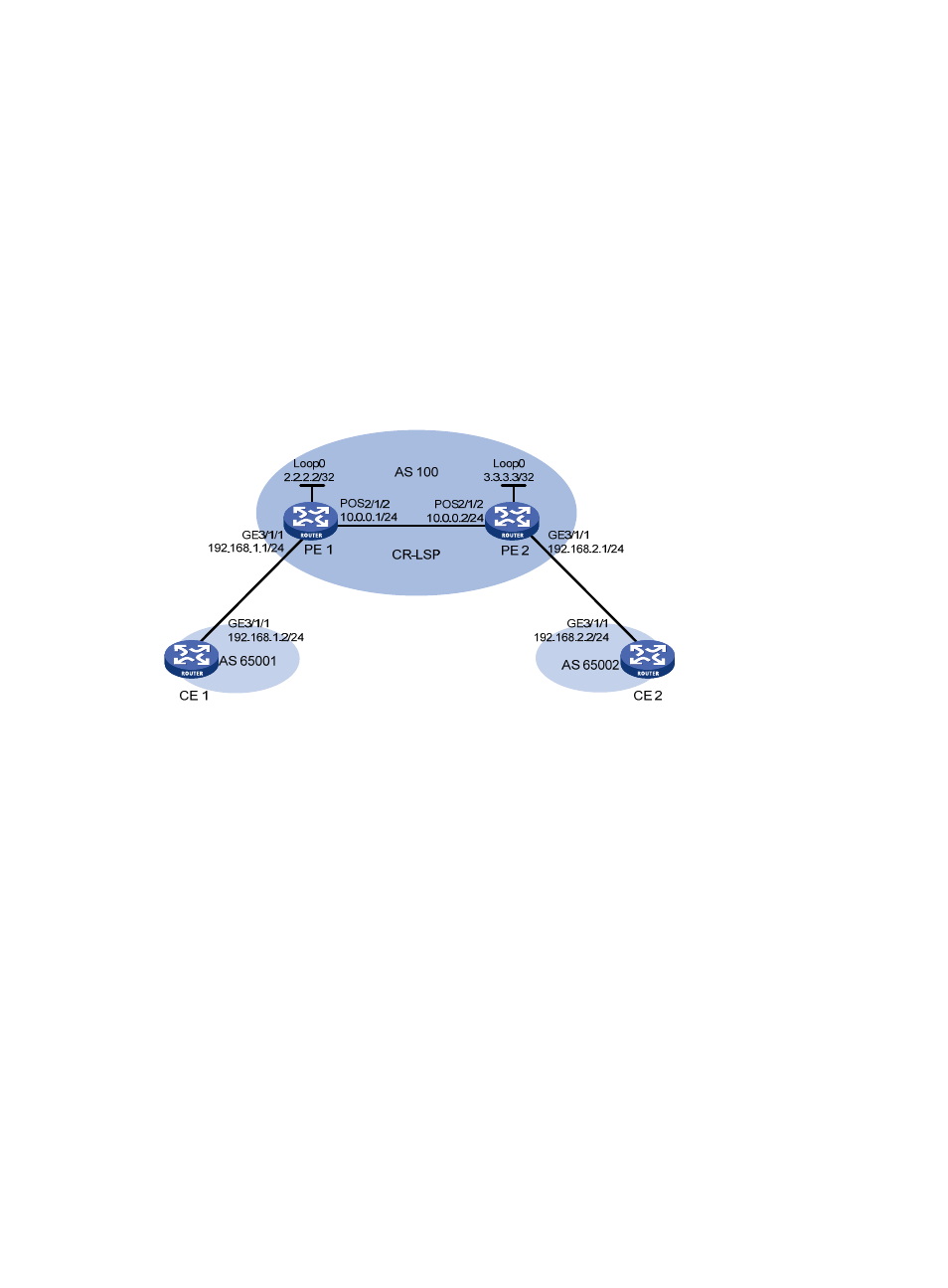
MPLS TE in MPLS L3VPN configuration example
Network requirements
CE 1 and CE 2 belong to VPN 1. They are connected to the MPLS backbone respectively through PE 1
and PE 2. The IGP protocol running on the MPLS backbone is OSPF.
Do the following:
•
Set up an MPLS TE tunnel to forward traffic of VPN 1 from PE 1 to PE 2.
•
To allow the MPLS L3VPN traffic to travel the TE tunnel, configure a tunneling policy to use a CR-LSP
as the VPN tunnel when creating the VPN.
Figure 34 Network diagram
Configuration procedure
1.
Configure OSPF, ensuring that PE 1 and PE 2 can learn routes from each other.
# Configure PE 1.
[PE1] interface loopback 0
[PE1-LoopBack0] ip address 2.2.2.2 255.255.255.255
[PE1-LoopBack0] quit
[PE1] interface pos 2/1/2
[PE1-POS2/1/2] clock master
[PE1-POS2/1/2] ip address 10.0.0.1 255.255.255.0
[PE1-POS2/1/2] quit
[PE1] ospf
[PE1-ospf-1] area 0
[PE1-ospf-1-area-0.0.0.0] network 10.0.0.0 0.0.0.255
[PE1-ospf-1-area-0.0.0.0] network 2.2.2.2 0.0.0.0
[PE1-ospf-1-area-0.0.0.0] quit
[PE1-ospf-1] quit
# Configure PE 2.