Configuration procedure – H3C Technologies H3C SR8800 User Manual
Page 390
379
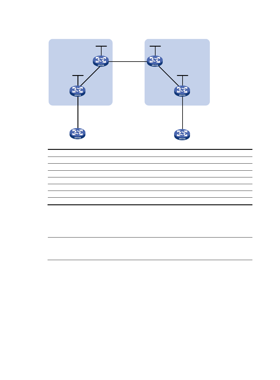
Figure 88 Network diagram
Device Interface
IP
address
Device
Interface IP
address
CE 1
GE4/1/1
2001:1::1/96
CE 2
GE4/1/1 2001:2::1/96
PE 1
Loop0
1.1.1.9/32
PE 2
Loop0
4.4.4.9/32
GE4/1/1
2001:1::2/96
GE4/1/1 2001:2::2/96
POS2/1/1
172.1.1.2/24
POS2/1/1 162.1.1.2/24
ASBR-PE1 Loop0 2.2.2.9/32
ASBR-PE2 Loop0 3.3.3.9/32
POS2/1/1
172.1.1.1/24
POS2/1/1 162.1.1.1/24
POS2/1/2
2002:1::1/96
POS2/1/2 2002:1::2/96
Configuration procedure
1.
Configure an IGP (such as OSPF) on each MPLS backbone to ensure IP connectivity within the
backbone. (Details not shown)
NOTE:
Be sure to advertise the route to the 32-bit loopback interface address of each router through OSPF. The
loopback interface address of a router is to be used as the router’s LSR ID.
After you complete the configurations, each ASBR PE and the PE in the same AS can establish an
OSPF adjacency. Issue the display ospf peer command and ping command; the output shows that
the adjacencies are in Full state, and that the PE and ASBR PE in the same AS have learned the
routes to the loopback interfaces of each other and can ping each other.
2.
Configure basic MPLS and enable MPLS LDP on each MPLS backbone to establish LDP LSPs.
# Configure basic MPLS on PE 1 and enable MPLS LDP for both PE 1 and the interface connected
to ASBR-PE 1.
[PE1] mpls lsr-id 1.1.1.9
[PE1] mpls
[PE1-mpls] quit
[PE1] mpls ldp
Loop0
Loop0
Loop0
Loop0
POS2/1/2
POS2/1/2
POS2/1/1
POS2/1/1
POS2/1/1
POS2/1/1
GE4/1/1
GE4/1/1
GE4/1/1
GE4/1/1
CE 1
CE 2
AS 65001
AS 65002
PE 1
PE 2
ASBR-PE 2
ASBR-PE 1
MPLS backbone
MPLS backbone
AS 100
AS 200