Configuration procedure – H3C Technologies H3C SR8800 User Manual
Page 307
296
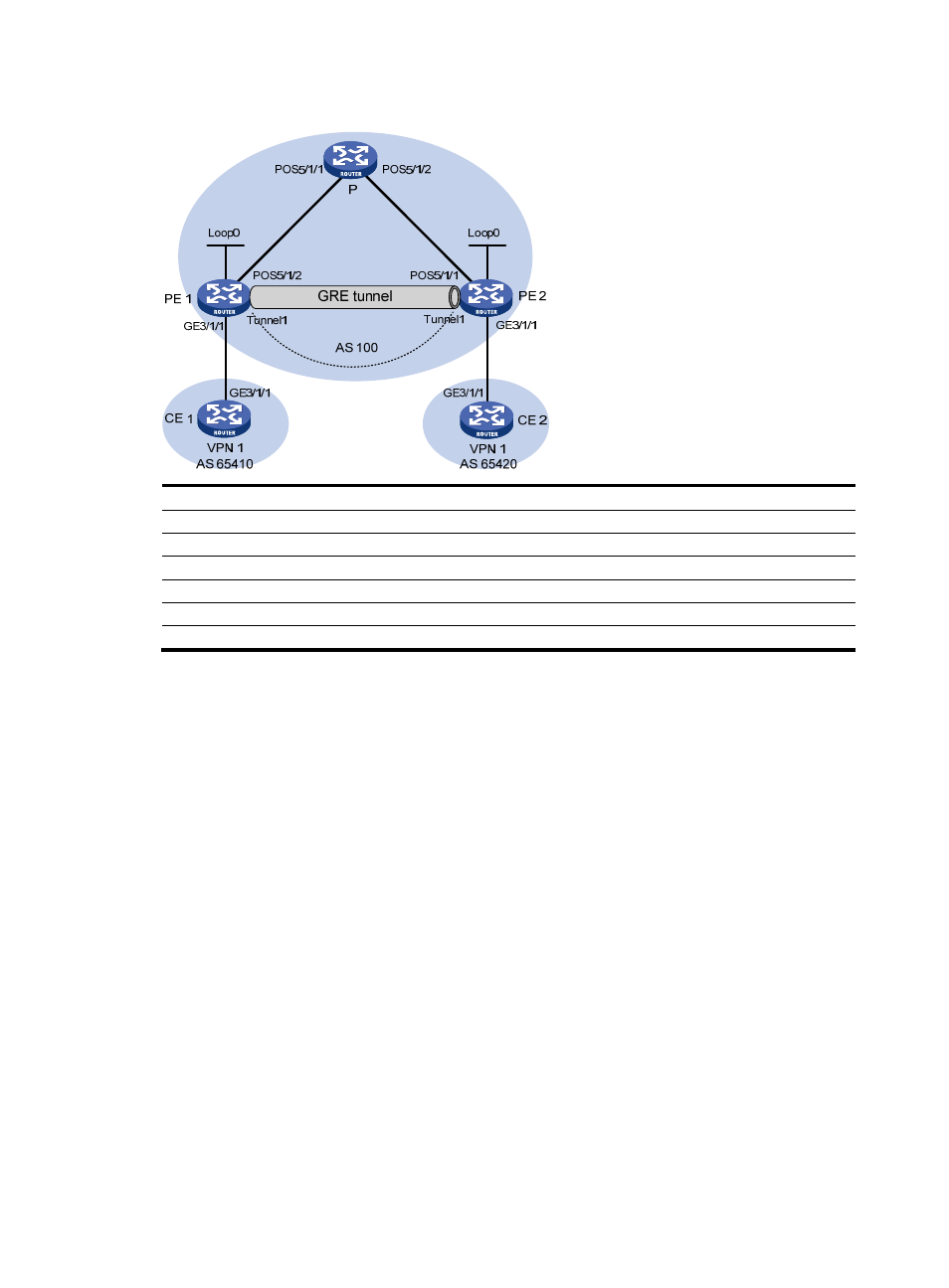
Figure 76 Network diagram
Device Interface IP
address
Device
Interface
IP address
CE 1
GE3/1/1
10.1.1.1/24
P
POS5/1/1
172.1.1.2/24
PE 1
Loop0
1.1.1.9/32
POS5/1/2 172.2.1.1/24
GE3/1/1
10.1.1.2/24
PE 2
Loop0
2.2.2.9/32
POS5/1/2
172.1.1.1/24
GE3/1/1
10.2.1.2/24
Tunnel0
20.1.1.1/24
POS5/1/1 172.2.1.2/24
CE 2
GE3/1/1
10.2.1.1/24
Tunnel0
20.1.1.2/24
Configuration procedure
1.
Configure an IGP (such as OSPF) on the MPLS backbone to ensure IP connectivity within the
backbone.
After you complete the configurations, OSPF adjacencies are established between PE 1, P, and PE
2. Issue the display ospf peer command. The output shows that the adjacency status is Full. Issue
the display ip routing-table command. The output shows that the PEs have learned the loopback
route of each other.
2.
Enable basic MPLS on the PEs
# Configure PE 1.
[PE1] mpls lsr-id 1.1.1.9
[PE1] mpls
[PE1-mpls] quit
# Configure PE 2.
[PE2] mpls lsr-id 2.2.2.9
[PE2] mpls
[PE2-mpls] quit
3.
Configure VPN instances on PEs to allow CEs to access, and apply tunneling policies to the VPN
instances, using a GRE tunnel for VPN packet forwarding
# Configure PE 1.