Configuring ospf sham links, Network requirements – H3C Technologies H3C SR8800 User Manual
Page 351
340
[SPE2-bgp] peer 4.4.4.9 next-hop-local
[SPE2-bgp] peer 2.2.2.9 as-number 100
[SPE2-bgp] peer 2.2.2.9 connect-interface loopback 0
[SPE2-bgp] ipv4-family vpnv4
[SPE2-bgp-af-vpnv4] peer 2.2.2.9 enable
[SPE2-bgp-af-vpnv4] peer 4.4.4.9 enable
[SPE2-bgp-af-vpnv4] peer 4.4.4.9 upe
[SPE2-bgp-af-vpnv4] quit
[SPE2-bgp]ipv4-family vpn-instance vpn1
[SPE2-bgp-vpn1] quit
[SPE2-bgp]ipv4-family vpn-instance vpn2
[SPE2-bgp-vpn2] quit
[SPE2-bgp] quit
# Configure SPE 2 to advertise to UPE 2 the routes permitted by a routing policy, that is, the routes
of CE 1.
[SPE2] ip ip-prefix hope index 10 permit 10.2.1.1 24
[SPE2] route-policy hope permit node 0
[SPE2-route-policy] if-match ip-prefix hope
[SPE2-route-policy] quit
[SPE2] bgp 100
[SPE2-bgp] ipv4-family vpnv4
[SPE2-bgp-af-vpnv4] peer 4.4.4.9 upe route-policy hope export
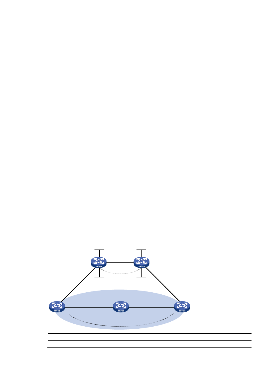
Configuring OSPF sham links
Network requirements
•
CE 1 and CE 2 belong to VPN 1 and are respectively connected to PE 1 and PE 2.
•
CE 1 and CE 2 are in the same OSPF area.
•
VPN traffic between CE 1 and CE 2 is required to be forwarded through the MPLS backbone,
instead of any route in the OSPF area.
Figure 83 Network diagram
Device Interface IP
address
Device
Interface
IP address
CE 1
GE4/1/1
100.1.1.1/24
CE 2
GE4/1/1
120.1.1.1/24
POS2/1/2
Loop0
Loop0
POS2/1/1
Sham-link
GE4/1/1
CE 1
Router A
CE 2
PE 2
PE 1
GE4/1/1
POS2/1/2
POS2/1/2
POS2/1/1
POS2/1/2
Loop1
Loop1
GE4/1/1
GE4/1/1
OSPF Area 1
Backdoor link