Configuration procedure – H3C Technologies H3C SR8800 User Manual
Page 121
110
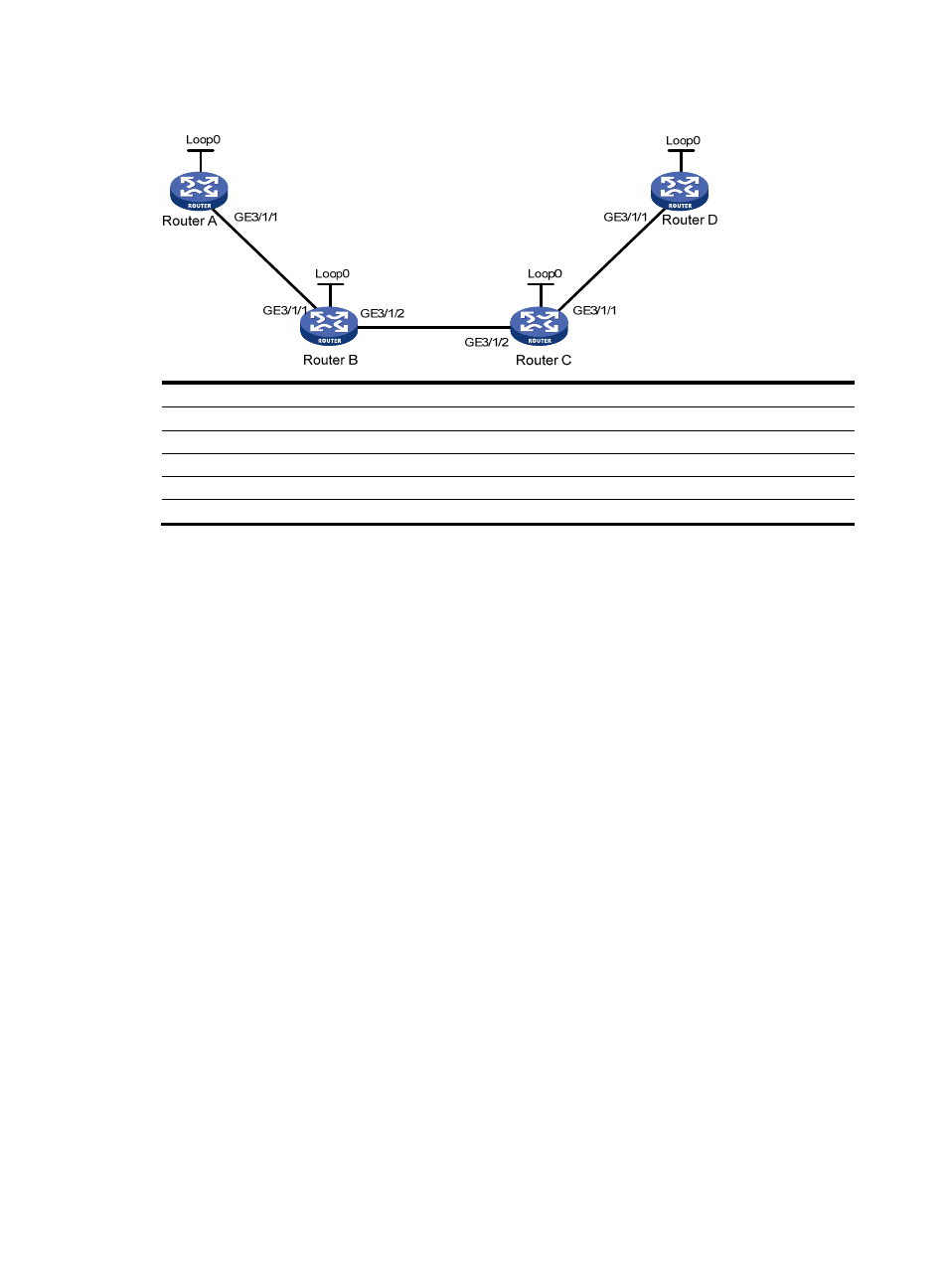
Figure 29 Network diagram
Device Interface IP
address
Device
Interface
IP address
Router A
Loop0
1.1.1.9/32
Router D
Loop0
4.4.4.9/32
GE
3/1/1
10.1.1.1/24
GE 3/1/1
30.1.1.2/24
Router B
Loop0
2.2.2.9/32
Router C
Loop0
3.3.3.9/32
GE 3/1/1
10.1.1.2/24
GE 3/1/1
30.1.1.1/24
GE
3/1/2
20.1.1.1/24
GE 3/1/2
20.1.1.2/24
Configuration procedure
1.
Assign IP addresses and masks to interfaces (see
)
Details not shown
2.
Enable OSPF to advertise host routes with LSR IDs as destinations
Details not shown
After configuration, you can perform the display ip routing-table command on each router. You
can see that all nodes learnt the host routes of other nodes with LSR IDs as destinations.
3.
Configure MPLS TE basic capabilities, and enable CSPF
# Configure Router A.
[RouterA] mpls lsr-id 1.1.1.9
[RouterA] mpls
[RouterA-mpls] mpls te
[RouterA-mpls] mpls te cspf
[RouterA-mpls] quit
[RouterA] interface GigabitEthernet 3/1/1
[RouterA-GigabitEthernet3/1/1] mpls
[RouterA-GigabitEthernet3/1/1] mpls te
[RouterA-GigabitEthernet3/1/1] quit
# Configure Router B.
[RouterB] mpls lsr-id 2.2.2.9
[RouterB] mpls
[RouterB-mpls] mpls te
[RouterB-mpls] mpls te cspf
[RouterB-mpls] quit
[RouterB] interface GigabitEthernet 3/1/1
[RouterB-GigabitEthernet3/1/1] mpls