Configuration procedure – H3C Technologies H3C SR8800 User Manual
Page 312
301
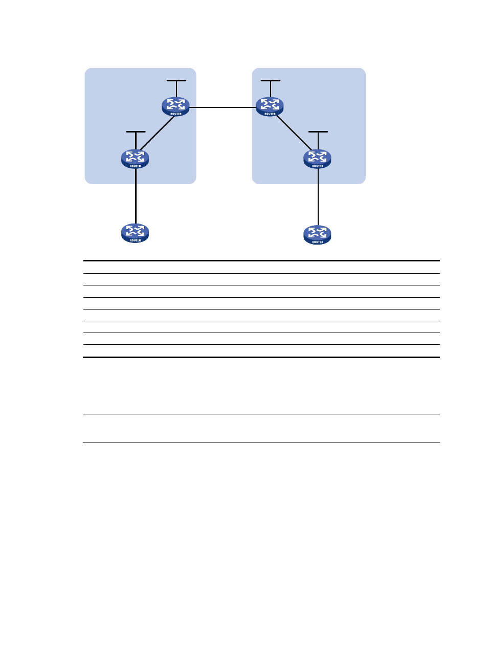
Figure 77 Network diagram
Device Interface
IP address
Device
Interface IP
address
CE 1
GE4/1/1
10.1.1.1/24
CE 2
GE4/1/1 10.2.1.1/24
PE 1
Loop0
1.1.1.9/32
PE 2
Loop0
4.4.4.9/32
GE4/1/2
10.1.1.2/24
GE4/1/2 10.2.1.2/24
POS2/1/1
172.1.1.1/24
POS2/1/1 162.1.1.1/24
ASBR-PE1 Loop0 2.2.2.9/32 ASBR-PE2 Loop0 3.3.3.9/32
POS2/1/1
172.1.1.2/24
POS2/1/1 162.1.1.2/24
POS2/1/2
192.1.1.1/24
POS2/1/2 192.1.1.2/24
Configuration procedure
1.
Configure an IGP (such as OSPF) on the MPLS backbone to ensure IP connectivity in the backbone.
(Details not shown)
NOTE:
The 32-bit loopback interface address used as the LSR ID needs to be advertised by OSPF.
After you complete the configurations, each ASBR PE and the PE in the same AS can establish
OSPF adjacencies. Issue the display ospf peer verbose command. The output shows that the
adjacencies reach the Full state, and that PEs can learn the routes to the loopback interfaces of
each other.
Each ASBR PE and the PE in the same AS can ping each other.
2.
Configure basic MPLS and MPLS LDP on the MPLS backbone to establish LDP LSPs
# Configure basic MPLS on PE 1 and enable MPLS LDP on the interface connected to ASBR PE 1.
[PE1] mpls lsr-id 1.1.1.9
[PE1] mpls
[PE1-mpls] quit
[PE1] mpls ldp
[PE1-mpls-ldp] quit
Loop0
Loop0
Loop0
Loop0
POS2/1/2
POS2/1/2
POS2/1/1
POS2/1/1
POS2/1/1
POS2/1/1
GE4/1/1
GE4/1/2
GE4/1/2
GE4/1/1
CE 1
CE 2
AS 65001
AS 65002
PE 1
PE 2
ASBR-PE 2
ASBR-PE 1
MPLS backbone
MPLS backbone
AS 100
AS 200