Mpls configuration examples, Configuring static lsps, Network requirements – H3C Technologies H3C SR8800 User Manual
Page 43: Configuration considerations, Configuration procedure
32
MPLS configuration examples
Configuring static LSPs
Network requirements
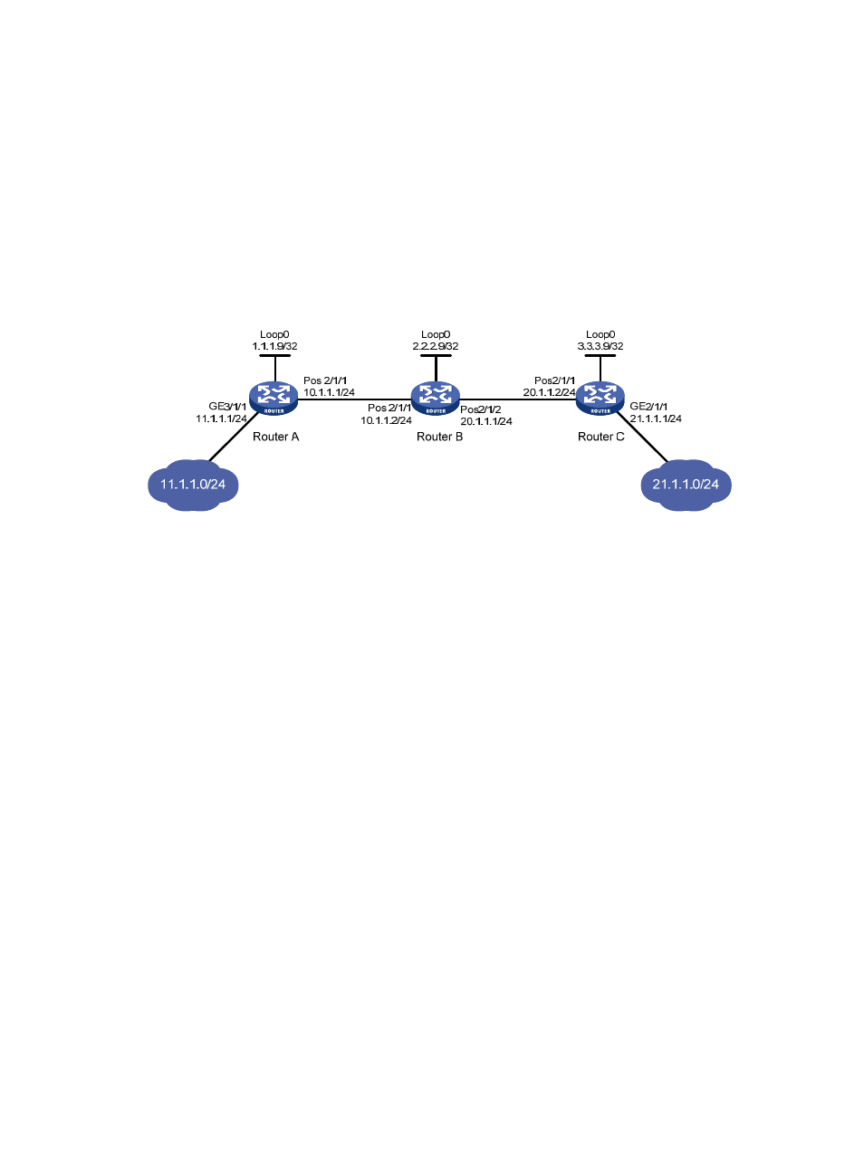
Router A, Router B, and Router C support MPLS.
Establish static LSPs between Router A and Router C so that subnets 10.1.1.0/24 and 21.1.1.0/24 can
access each other over MPLS. Check the connectivity of the static LSPs.
Figure 13 Network diagram
Configuration considerations
•
On an LSP, the outgoing label of an upstream LSR must be identical with the incoming label of its
downstream LSR.
•
Configure an LSP for each direction on the forwarding path.
•
Configure a static route to the destination address of the LSP on each ingress node. There is no need
to configure such a static route on the transit and egress nodes and thus you do not need to
configure any routing protocol on the routers.
Configuration procedure
1.
Configure the IP addresses of the interfaces.
Configure the IP addresses and masks of the interfaces including the loopback interfaces as
required in
. (Details not shown)
2.
Configure a static route to the destination address of the FEC on each ingress node.
# Configure a static route to network 21.1.1.0/24 on Router A.
[RouterA] ip route-static 21.1.1.0 24 10.1.1.2
# Configure a static route to network 11.1.1.0/24 on Router C.
[RouterC] ip route-static 11.1.1.0 255.255.255.0 20.1.1.1
3.
Enable MPLS.
# Configure MPLS on Router A.
[RouterA] mpls lsr-id 1.1.1.9
[RouterA] mpls
[RouterA-mpls] quit