Configuration procedure – H3C Technologies H3C SR8800 User Manual
Page 148
137
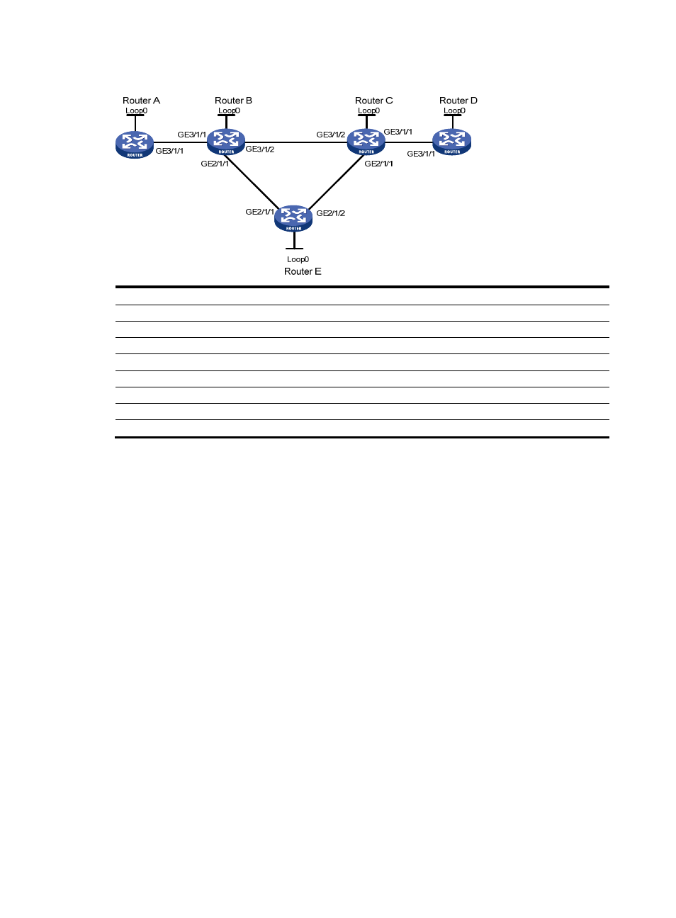
Figure 33 Network diagram
Device Interface IP
address
Device
Interface
IP address
Router A
Loop0
1.1.1.1/32
Router E
Loop0
5.5.5.5/32
GE3/1/1
2.1.1.1/24
GE2/1/1
3.2.1.2/24
Router B
Loop0
2.2.2.2/32
GE2/1/2 3.3.1.1/24
GE3/1/1
2.1.1.2/24
Router C
Loop0
3.3.3.3/32
GE3/1/2
3.1.1.1/24
GE3/1/1
4.1.1.1/24
GE2/1/1
3.2.1.1/24
GE3/1/2 3.1.1.2/24
Router D
Loop0
4.4.4.4/32
GE2/1/1 3.3.1.2/24
GE3/1/1
4.1.1.2/24
Configuration procedure
1.
Assign IP addresses and masks to interfaces (see
)
Details not shown
2.
Configure the IGP protocol
Enable OSPF on each router to advertise subnets to which interfaces belong and the host routes
with LSR IDs as destinations. (Details not shown)
3.
Configure MPLS LDP basic capabilities on Router A and Router D
Details not shown
4.
Configure MPLS TE basic capabilities and enable RSVP-TE and CSPF on Router B, Router C and
Router E
# Configure Router B.
[RouterB] mpls lsr-id 2.2.2.2
[RouterB] mpls
[RouterB-mpls] mpls te
[RouterB-mpls] mpls rsvp-te
[RouterB-mpls] mpls te cspf
[RouterB-mpls] quit
[RouterB] interface GigabitEthernet 2/1/1
[RouterB-GigabitEthernet2/1/1] mpls
[RouterB-GigabitEthernet2/1/1] mpls te
[RouterB-GigabitEthernet2/1/1] mpls rsvp-te