AMETEK Compact i/iX Series Software Manual User Manual
Page 56
User Manual
– Rev H
California Instruments
56
Avionics Software
No.
Description
115
VAC
235
VAC
No.
28 VDC Tests
Description
Type
I DC
Type
II DC
Type
III DC
Type
IV DC
Type
V DC
Type
VI DC
Transient Tests
1.8
Frequency Modulation
9.1.1
13.1
Steady State Voltage
2.1
Voltage Transients
9.1.2
Steady State Voltage
N/A
2.2
Voltage Spikes
X
X
9.2.1
Differential Mode
Voltage Ripple
TBD
N/A
2.3.1
Maximum Ramp Rate
9.2.2
13.3
Differential Mode
Ripple Components
X
X
2.3.2
Frequency Transients
9.3.1
13.2
Common Mode
Voltage
TBD
2.4
Multiple Stroke Power
Interruptions
9.3.2
Common Mode
Frequency
X
N/A
3.1
Abnormal Individual
Phase Voltage
10.1
14.1
Voltage Transients
3.2
Abnormal Average of
Three Phase Voltages
11.1
15.1
Abnormal Steady State
Voltage
4.1
Abnormal Voltage
Transients
11.2.1
Abnormal Differential
Mode Ripple
X
N/A
4.2.1
Abnormal Maximum
Ramp Rate
12.1
16.1
Abnormal Voltage
Transients
4.2.2
Abnormal Frequency
Transients
4.3
Abnormal DC Content
P
P
Supp
Supplementary
Transient Tests
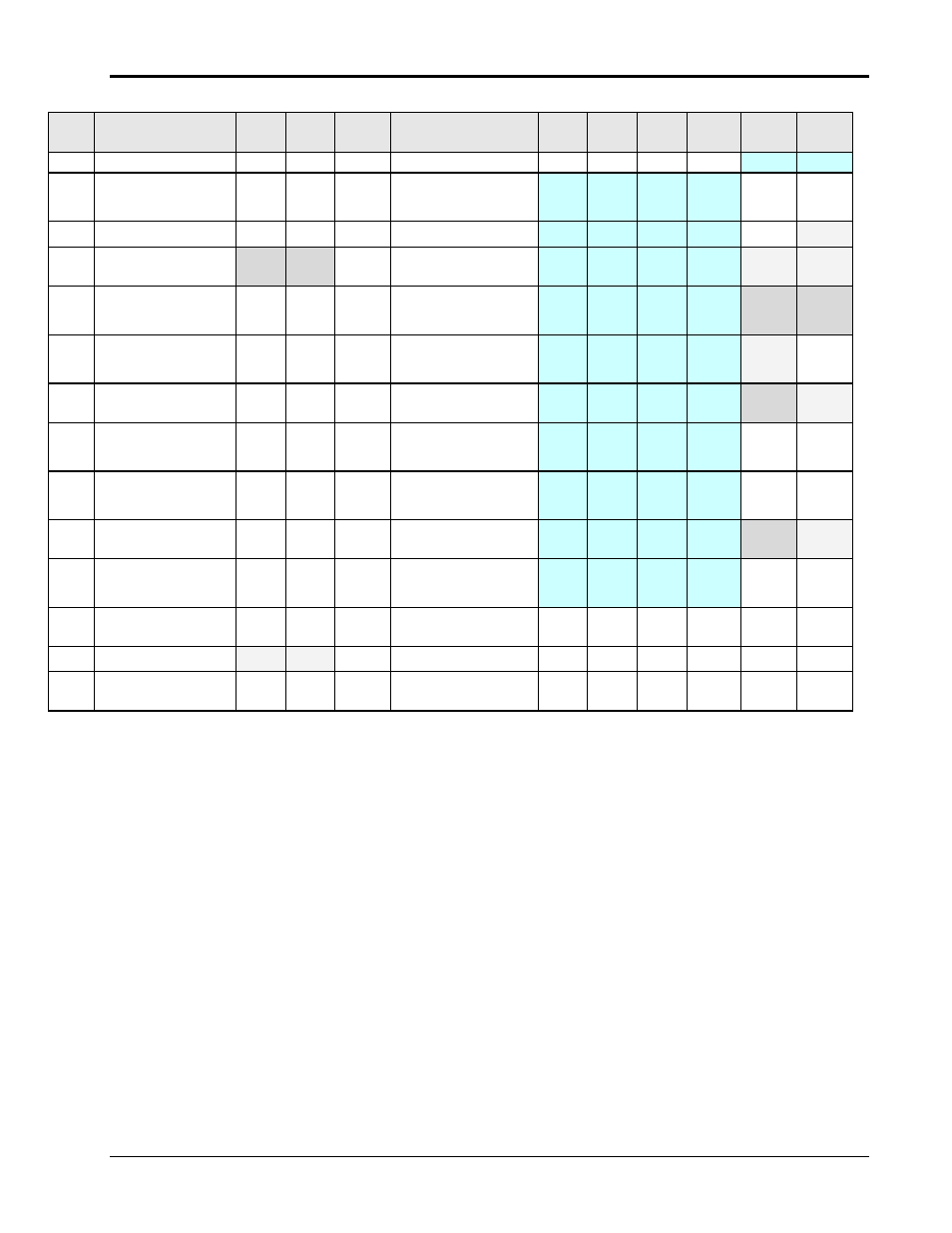
Table 4-1: -B787 Option MX Test Coverage
Note that some AC tests requiring more than 300Vrms output will require the
–HV (400 Vrms)
optional output range.