Option –704: mil-std-704 rev a, b, c, & f tests, Test coverage, Mx series -704 option limitations – AMETEK Compact i/iX Series Software Manual User Manual
Page 101: Option, Mil-std-704 rev a, b, c, & f tests, 1 test coverage

User Manual - Rev H
California Instruments
Avionics Software
101
5 Option
–704: MIL-STD-704 rev A, B, C, & F Tests
The -704 option supports MIL-STD-704 revs A, B, C, and F voltage and frequency immunity tests in
either of the AC or DC mode (if available).
The
–704 option is based on MIL-STD-704 Department of Defense Interface Standard: Aircraft
Electric Power Characteristics Appendix A dated March 2004.
Future revisions of the MIL-STD-704 directive may be issued over time and updates may be made
available to cover any changes in test levels, durations, procedures etc. Furthermore, the
–704 option
is completely data file driven to allow a large degree of customization by the end-user if needed so
many changes can be supported without the need for software updates.
This section of the manual explains the limitations of this test option, the use of special features
unique to this option, and gives a complete layout of all tests performed by this option.
This manual is not intended to elaborate on the intent or purpose of the immunity tests and the
expected behavior of the EUT as described in the MIL-STD-704 documents. It is assumed that the
end-user is familiar with the content of the MIL-STD-704 test standard.
Note: All three phase California Instruments power sources have a phase rotation of A C B where
phase C is +120° from phase A and phase B is +240° from phase A. Some interpretations of this
specification call for phase B to be +120° from phase A. The easiest way to accomplish a ABC phase
rotation is to simply switch phase B and phase C wires at the EUT input. Alternatively, the
programmed phase angles for B and C can be changed but this will require editing of the test scripts
and is not recommended.
5.1 Test Coverage
The comprehensiveness of the test that can be performed with the
–704 option is determined
primarily by the capabilities of the power source used. Tests that are outside the hardware capabilities
of the power source used will not be enabled and cannot be selected. For these tests, additional
equipment may be required as indicated.
5.1.1
MX Series -704 Option Limitations
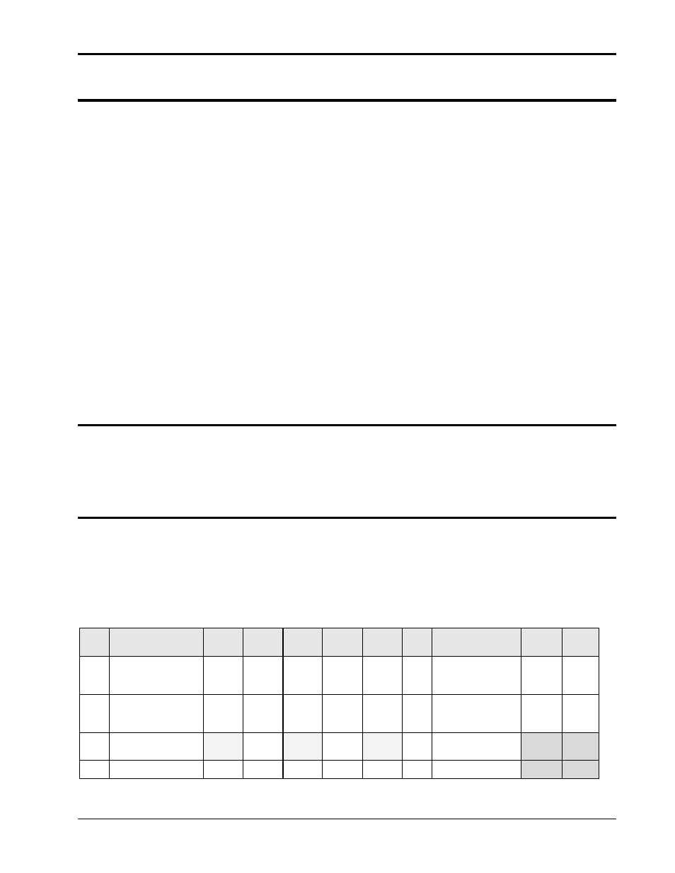
The extent of coverage of the
–704 option as implemented on the MX Series platform is shown in the
table below. Tests marked with an „x‟ generally require additional hardware to be used. Tests marked
„N/A‟ are not applicable to the corresponding table. Tests marked with a „
‟ are covered by at least
one rev of the MIL-STD-704. Additional implementation issues may apply as well as indicated in
section 5.1.1.1.
Tests marked with a „P‟ require arbitrary waveform capability, which is available on Pi
models or base models with the
–ADV option only. Note: The MX15 Series power sources are single
phase output only and therefore all three phase tests are not available on the MX15.
No.
Description
Table
SAC
Table
TAC
Table
SVF
Table
TVF
Table
SXF
No.
Description
Table
LDC
Table
HDC
101
Load and Current
Harmonic
Measurements
101
Load
Measurements
102
Steady State Limits
for Voltage and
Freq.
102
Steady State Limits
for Voltage
103
Voltage Phase
Difference
N/A
N/A
N/A
103
Voltage Distortion
Spectrum
X
X
104
Voltage Modulation
104
Total Ripple
X
X
