Table tcf – AMETEK Compact i/iX Series Software Manual User Manual
Page 199

User Manual - Rev H
California Instruments
Avionics Software
199
8.4.1.4
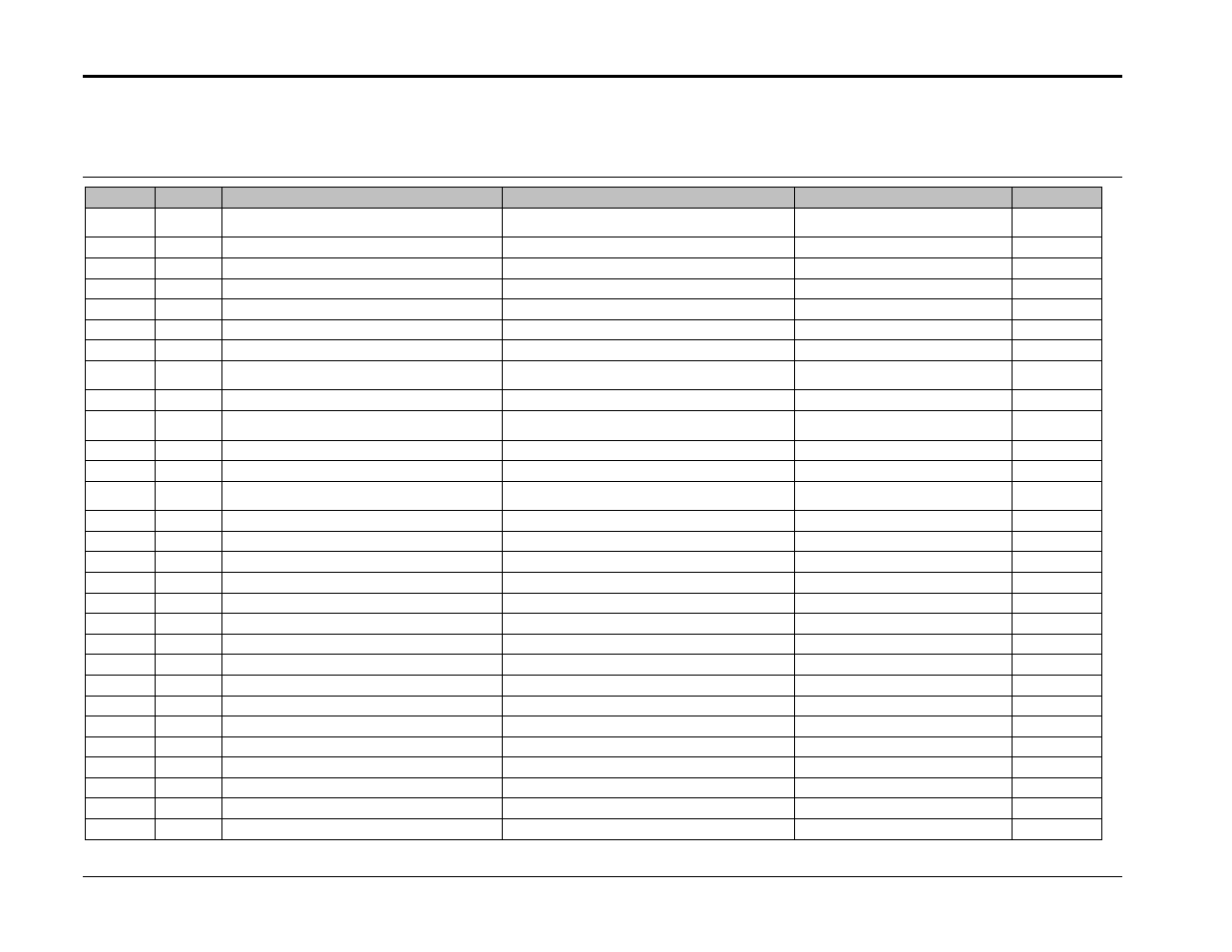
Table TCF:
Test No.
Section
Subject
Test Limits
Comment
File Ref.
TCF101
Steady State Voltage and Frequency
104 to 122 Volts RMS
DO160 16.5.1.1.b, 410Hz and
390Hz
TCF101
TCF102
Voltage Transients
Surge to 160Vac max, Sag to 71Vac min
DO160 16.5.1.5.1.b, 400Hz
TCF102
TCF103
Voltage Modulation
Vamp = 0.18V to 1.24V, Mrate = 1Hz to 200Hz
DO160 16.5.1.2, 400Hz
TCF103
TCF104
Voltage Spikes
Requires Additional Equipment
TCF105
Current Distortion
115Vnom, 400 Hz
Limits defined by Table A.5
TCF105
TCF106
Voltage Distortion
10% distortion
30sec each frequency
TCF106
TCF106
EW
Voltage Distortion - Endurance test with motor
10% distortion
Per Table TCF 106-2
TCF106-EW
TCF106
E
Voltage Distortion - Endurance test without
motor
10% distortion
Per Table TCF 106-2
TCF106-E
TCF107
Inrush Current
Test requires multiple load cables
Test not performed with software
TCF108
Frequency Modulation
Famp = 4.9 Hz to 0.2Hz, Mrate = 0.014Hz to
100Hz
DO160 16.5.1.3, 400Hz
TCF108
TCF109
Voltage DC Content
+/-.3VDC Offset
30 mins each test
TCF109
TCF110
Voltage Modulation due to Equipment
Test requires special cables
Test not performed with software
TCF111
Voltage Spike Due to Equipment Load
Switching
Requires Additional Equipment
TCF201
Abnormal Steady State Voltage and Frequency
96 to 130 Volts RMS
DO160 16.5.2.1.b, 400Hz
TCF201
TCF202
Abnormal Voltage Transients
Surge to 180Vac max, Sag to 0Vac min
DO160 16.5.2.2.b, 400Hz
TCF202
TCF203
Abnormal Voltage Modulation
Vamp = 0.18V to 1.24V, Mrate = 1Hz to 200Hz
DO160 16.5.1.2, 400Hz
TCF203
TCF204
Abnormal Frequency Variations
320Hz to 480Hz
TCF204
TCF401
Transparency Time
10ms dropouts
Per Figure TCF 401-1
TCF401
TCF402
Voltage Switching Transients 1
Test Conditions 1-17, 400Hz
Per Figure TCF 402-1
TCF402-1
TCF402
Voltage Switching Transients 1
Test Conditions 18-27, 400Hz
Per Figure TCF 402-1
TCF402-2
TCF402
Voltage Switching Transients 1
Test Conditions 28-36, 400Hz
Per Figure TCF 402-1
TCF402-3
TCF402
Voltage Switching Transients 1
Test Conditions 37-42, 400Hz
Per Figure TCF 402-1
TCF402-4
TCF403
Voltage Switching Transients 2
T=1 to T=49, 400Hz
Per Figure TCF 403-1
TCF403-1
TCF403
Voltage Switching Transients 2
T=50 to T=99, 400Hz
Per Figure TCF 403-1
TCF403-2
TCF403
Voltage Switching Transients 2
T=100 to T=200, 400Hz
Per Figure TCF 403-1
TCF403-3
TCF501
Power Failure
Test requires physically removing line cables
Test not performed with software
