Test selection, 3 test selection – AMETEK Compact i/iX Series Software Manual User Manual
Page 13
User Manual - Rev H
California Instruments
Avionics Software
13
2.3 Test Selection
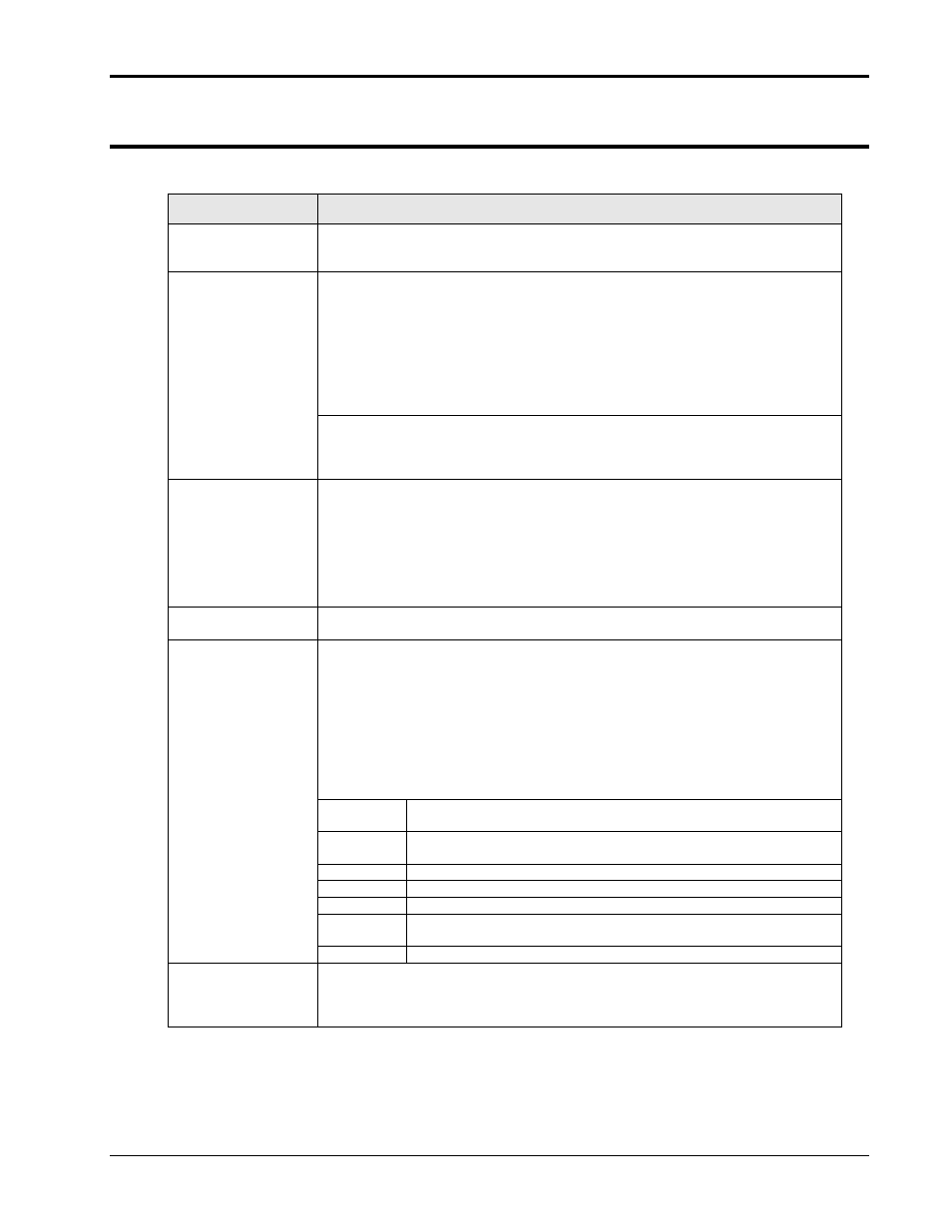
The Test Selections tab in the test control window contains the following controls and displays.
Control / Display
Description
Select Revision.
This drop down control allows the operator to select from one or more libraries of
test sequences grouped by revision. The GUI program is supplied with
predefined revisions of test sequences.
Power Group Test
Table
A library can contain a number of power group test tables. These table names
correspond to the Power Groups identified in the specific standard, and are listed
in their section of this manual. The operator cannot select a group that is not
supported by the present mode of operation of the power source. Thus, if the
power source is in AC mode, an error message will be displayed when trying to
select a DC group. Operating modes such as AC or DC must be changed from
the main GUI screen. The test control screen can remain open while switching
back to the main screen. Upon return to the test control screen, the relevant
power groups can be selected.
The operator needs to determine what the relevant power group selection is for
the unit under test. (EUT). When switching power groups, the table data shown at
the bottom of this tab will be updated to reflect the new selection. The first test
section of the table will automatically be selected when switching power groups.
Present Power
Source Output
Settings
This section displays the programmed steady state settings that are in effect.
This information is updated each time the test control form regains focus. The
mode of operation (AC, DC or AC+DC) is displayed for reference but cannot be
changed from this screen. When in DC mode, the frequency setting will show
“DC”.
Note that changes in steady state settings can only be made from the main GUI
screen. The operator can toggle between the main screen and the test control
screen for this purpose as needed.
Table Header
The table header is shown against a blue background and contains the table
reference designator and a description of the selected power group.
Test Table Display
The data grid at the bottom of the tab displays the selected power group test
table. It is also used to select the specific test section and number to be
executed. Thus, every test starts by selecting the desired test step from this
table. Clicking on the desired ROW does this. The selected row will be
highlighted and the associated file shown in the File Ref. Field will be loaded in
the Test Control tab.
For better readability, the user can adjust the column widths by dragging the
dividers between columns. If the window is too small to display all rows and
columns, scroll bars will appear at the bottom and/or right of the data grid.
The following fields are displayed in the test data tables.
Test
Number of the test from the avionics standard. For sub sections of
a test number, this field will be blank.
Section
Test section. Some tests may only have one section in which case
this field is blank.
Subject
Description of the type of test.
Test Limits
A summary of the test limits that will be applied by this test.
Comment
Comments concerning this test or its parameters.
File
Reference
The test sequence file that is used to implement this test section
on the power source.
User Data
The area at the bottom of this tab may be used to enter general information
regarding the unit under test, the test location and operator and environmental
conditions in effect during the test. This information will be incorporated in the
test reports generated by the GUI.