Specific test limitations and discrepancies, I/ix series –amd option limitations – AMETEK Compact i/iX Series Software Manual User Manual
Page 188

User Manual
– Rev H
California Instruments
Avionics Software
188
8.1.1.1
Specific Test Limitations and Discrepancies
While every effort has been made to provide comprehensive coverage of the Airbus AMD tests, some
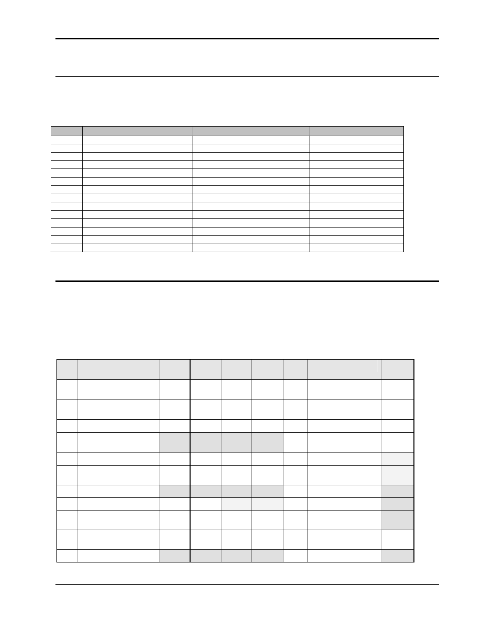
limitations apply, largely due to hardware limitations of the MX power source. The following table lists
specific implementation issues by test number. The deviation from the standard requirement is shown
in the “Actual setting” column. The reason for the deviation is shown in the last column.
Test
Standard requirement
Actual setting
Reason
SVF103
115 +/- .18 Vrms
115 +/- .2 Vrms
Resolution
SVF103
115 +/- 1.24 Vrms
115 +/- 1.2 Vrms
Resolution
TVF103
115 +/- .18 Vrms
115 +/- .2 Vrms
Resolution
TVF103
115 +/- 1.24 Vrms
115 +/- 1.2 Vrms
Resolution
SCF103
115 +/- .18 Vrms
115 +/- .2 Vrms
Resolution
SCF103
115 +/- 1.24 Vrms
115 +/- 1.2 Vrms
Resolution
TCF103
115 +/- .18 Vrms
115 +/- .2 Vrms
Resolution
TCF103
115 +/- 1.24 Vrms
115 +/- 1.2 Vrms
Resolution
SVF103
390Hz mod by .75Hz
390Hz mod by .8Hz
Resolution
SVF103
620Hz mod by .75Hz
620Hz mod by .8Hz
Resolution
TVF103
390Hz mod by .75Hz
390Hz mod by .8Hz
Resolution
TVF103
620Hz mod by .75Hz
620Hz mod by .8Hz
Resolution
SCF103
400Hz mod by .75Hz
400Hz mod by .8Hz
Resolution
TCF103
400Hz mod by .75Hz
400Hz mod by .8Hz
Resolution
8.1.2
i/iX Series
–AMD Option Limitations
The extent of coverage of the
–AMD option as implemented on the iX Series platform is shown in the
table below. Tests marked with an „x‟ generally require additional hardware to be used. Tests marked
„N/A‟ are not applicable to the corresponding table. Tests marked with a „
‟ are covered by the –AMD
tests. Tests marked with an „I‟ apply to standard iX series products only and are not available on
Compact iX products.
Tests marked with a „P‟ require arbitrary waveform capability, which is
available on iX models or base models with the
–ADV option only. Additional implementation issues
may apply as well as indicated in section 8.1.2.1.
No.
Description
Table
SVF
Table
TVF
Table
SCF
Table
TCF
No.
Description
Table
LDC
101
Steady State Voltage and
Frequency
101
Steady State Voltage
102
Voltage Transients
101-
APU
Steady State Voltage
103
Voltage Modulation
102
Voltage Transients
104
Voltage Spikes
X
X
X
X
102-
APU
Voltage Transients
105
Current Distortion
103
Voltage Ripple
I
106
Voltage Distortion
P
P
P
P
103-
APU
Voltage Ripple
I
107
Inrush Current
X
X
X
X
104
Voltage Spikes
X
108
Frequency Variations
N/A
N/A
105
Inrush Current
X
109
Frequency Modulation
105-
APU
Inrush Current
X
110
Voltage DC Content
P or
C,x
P or
C,x
P or
C,x
P or
C,x
106
Voltage Variations Due
to APU Starting
111
Voltage Modulation Due
X
X
X
X
107
DC Ripple Due to
X
