Ctc interrupt servicing, Overview, Figure 11. ctc counting and timing – Zilog Z08470 User Manual
Page 45: Ctc interrupt servicing overview
< %27 2GTKRJGTCNU
7UGT /CPWCN
UM008101-0601
Counter/Timer Channels
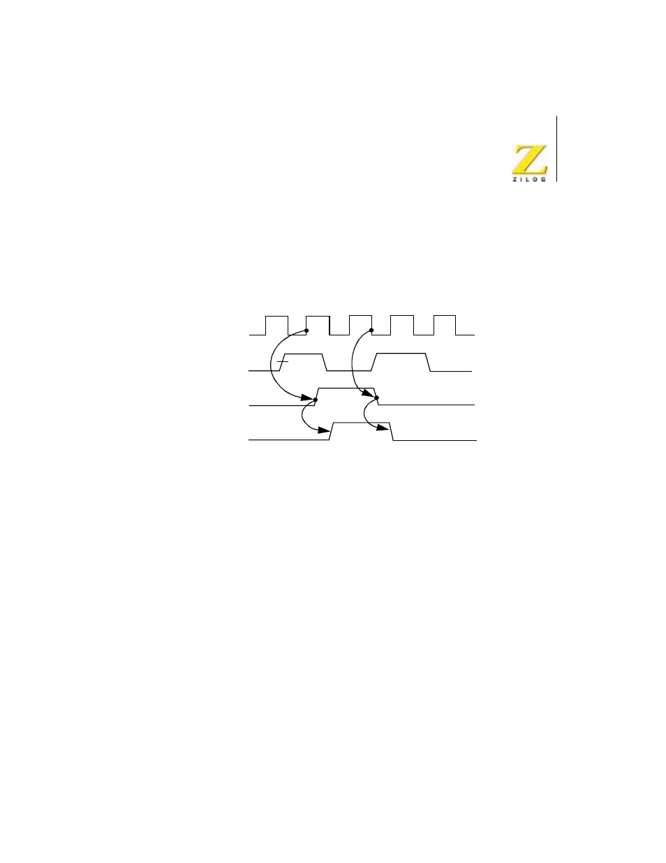
detected asynchronously and must have a minimum width. The timing
function is initiated in synchronization with
Φ. A minimum setup time is
required between the active edge of the CLK/TRG and the rising edge of
Φ.
If the CLK/TRG edge occurs closer than this, the initiation of the timer
function will be delayed one cycle of
Φ.
Figure 11.
CTC Counting and Timing
CTC INTERRUPT SERVICING
Overview
Each CTC channel may be individually programmed to request an
interrupt every time its down-counter reaches zero. The purpose of a CTC-
generated interrupt is to force the CPU to execute an interrupt service
routine. To use this feature the Z80 CPU must be programmed for Mode 2
interrupt response. In this mode, when a CTC channel interrupt request is
acknowledged, a 16-bit pointer must be formed to obtain a corresponding
interrupt service routine. The lower eight bits of the pointer are provided
by the CTC in the form of an interrupt vector unique to the requesting
channel. For further details, refer to the Z80 CPU User’s Manual.
ZC/TO
CLK/TRG
Internal
Counter
Lead
Time
Zero
Count