Sdlc transmit, Initialization – Zilog Z08470 User Manual
Page 276
< %27 2GTKRJGTCNU
7UGT /CPWCN
UM008101-0601
Serial Input/Output
256
The control field of the SDLC frame is transparent to the Z80 SIO, and it
is transferred to the CPU. The Z80 SIO handles the Frame Check
sequence in a way that simplifies the program by incorporating features,
such as initializing the CRC generator to all 1s, resetting the CRC checker
when the opening flag is detected in the Receive mode, and sending the
Frame Check/Flag sequence in the Transmit mode. Controller hardware is
simplified by automatic zero insertion and deletion logic contained in the
Z80 SIO.
lists the contents of WR3, WR4, and WR5 during SDLC Receive
and Transmit modes. WR0 points to other registers and issues commands.
WR1 defines the interrupt modes. WR2 stores the interrupt vector. WR7
stores the flag character and WR6 the secondary address.
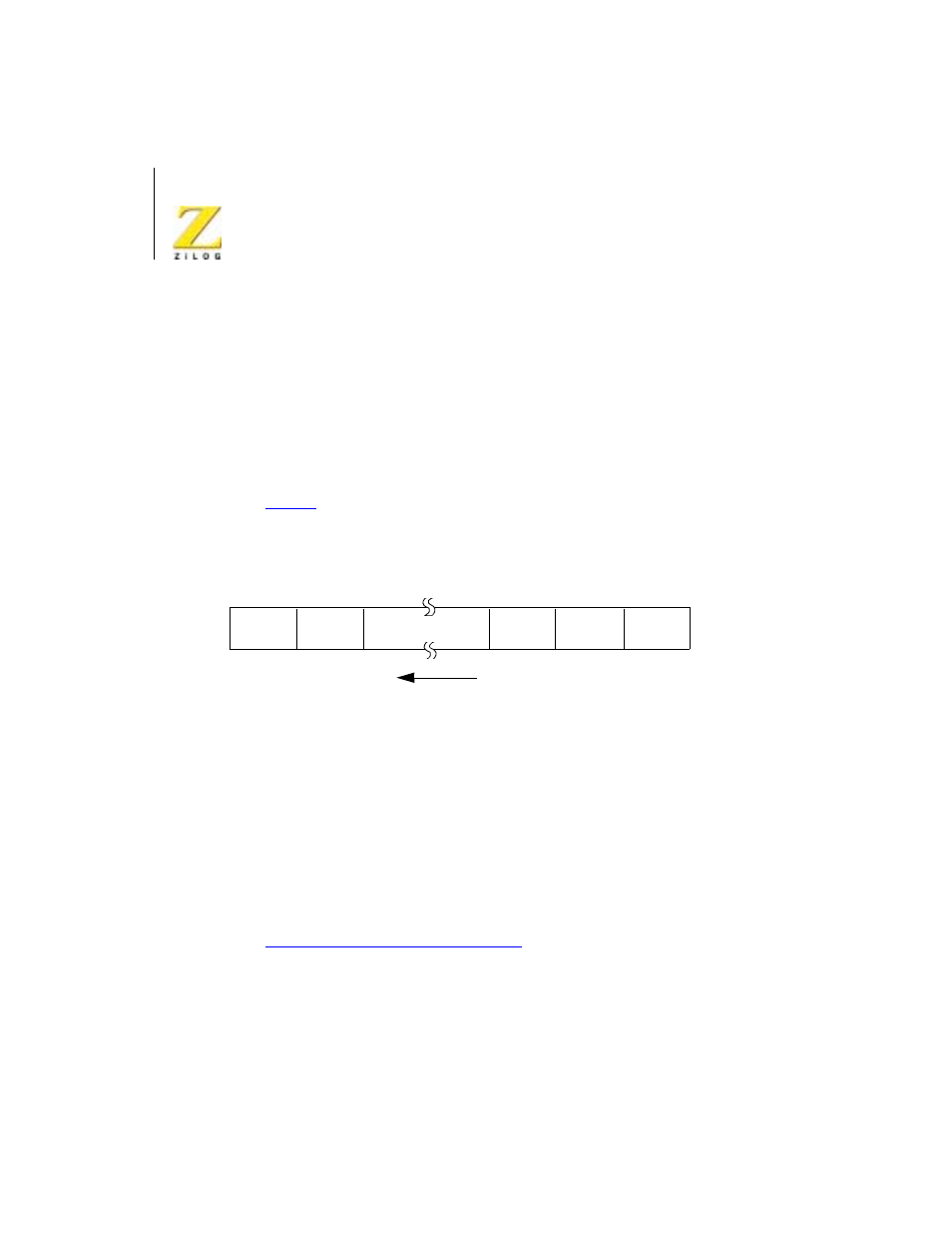
Figure 113. Transmit/Receive SDLC/HDLC Message Format
SDLC Transmit
Initialization
The SDLC Transmit mode must be initialized with the following parame-
ters: SDLC mode, SDLC polynomial, Request To Send, Data Terminal
Ready, transmit character length, transmit interrupt modes (or Wait/Ready
function), Transmit Enable, Auto Enables, and External/Status interrupt. Se
“SDLC Transmit Mode” on page 262
Selecting the SDLC mode and the SDLC polynomial allows the Z80 SIO to
initialize the CRC Generator to all 1s. Initialization is accomplished by
issuing the Reset Transmit CRC Generator command WR0. Refer to the
Beginning
Opening
Flag
0111 1110
Address
8 Bits
CRC
15
#1
8 7
0
CRC
#2
Closing
Flag
0111 1110
End
Message Flow
Data Field or
I-Field