Bidirectional mode (mode 2), Figure 91. mode 1 (input) timing – Zilog Z08470 User Manual
Page 214
< %27 2GTKRJGTCNU
7UGT /CPWCN
UM008101-0601
Parallel Input/Output
PIO. If already active, Ready is forced low for one and one-half
Φ periods
following the leading edge of IORQ during a read of a PIO port.
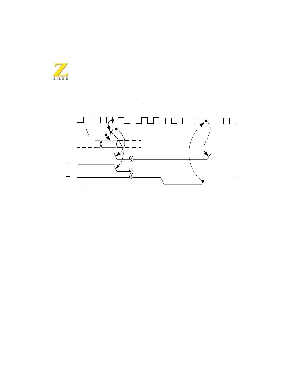
Figure 8.
Mode 1 (Input) Timing
Bidirectional Mode (Mode 2)
This mode is a combination of Mode 0 and Mode 1, using all four hand-
shake lines. Because this mode requires all four lines, it is available only on
Port A. When this mode is used on Port A, Port B must be set to the Bit
Control Mode. The same interrupt vector is returned for a Mode 3 interrupt
on Port B and an input transfer interrupt during Mode 2 operation of Port A.
Ambiguity is avoided if Port B is operated in a polled mode and the Port B
mask register is set to inhibit all bits.
Figure 9 illustrates the timing for this mode. It is almost identical to that
previously described for Mode 0 and Mode 1 with the Port A handshake
lines used for output control and the Port B lines used for input control. The
difference between the two modes is that, in Mode 2, data is allowed out
onto the bus only when the A strobe is Low. The rising edge of this strobe
can be used to latch the data to the peripheral because the data remains stable
Ready
Port Input
(8 Bits)
Strobe
INT
RD*
Φ
Sample
RD* = RD • CE • C/D • IORQ