Table 16, Sample dma program – Zilog Z08470 User Manual
Page 145
< %27 2GTKRJGTCNU
7UGT /CPWCN
UM008101-0601
Direct Memory Access
completed before the next
READ STATUS BYTE
or
INITIATE READ
SEQUENCE
command.
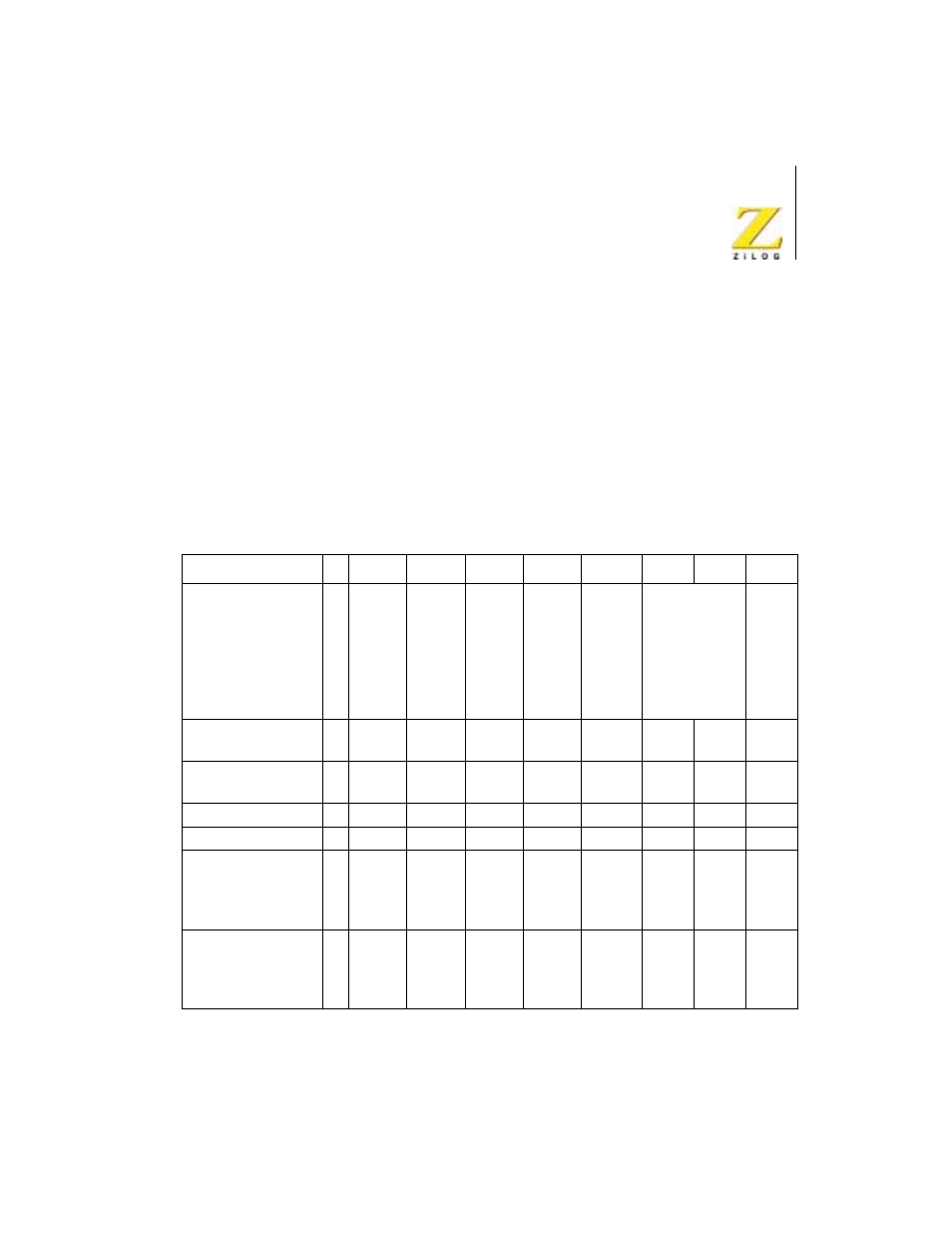
Table 16 illustrates a program to transfer data from memory (Port A) to a
peripheral device (Port B). In this example, the Port A memory starting
address is
1050H
and the Port B peripheral fixed address is
05H
. The
number of data bytes to be transferred is
1001H
bytes (one more than spec-
ified by the block length). The table of DMA commands may be stored in
consecutive memory locations and transferred to the DMA with an output
instruction such as the Z80 CPU’s OTIR instruction.
Table 16. Sample DMA Program
D7
D5
D4
D3
D2
D1
D0
HEX
WR0 sets DMA to
receive block length,
Port A starting
address, and
temporarily sets Port
B as source.
0
1
Block
Length
Upper
Follows
1
Block
Length
Upper
Follows
1
Port A
Upper
Address
Follows
1
Port A
Upper
Address
Follows
0
B
→A
Tempor
ary for
Leading
B
Address
0
Transfer. No
Search
Port A address
(lower)
0
1
0
1
0
0
0
0
50
Port A address
(upper)
0
0
0
1
0
0
0
0
10
Block length (lower)
0
0
0
0
0
0
0
0
00
Block length (upper)
0
0
0
1
0
0
0
0
10
WR1 defines Port A
as memory with
fixed incrementing
address
0
0
No
Timing
Follows
0
Address
Change
s
1
Address
Change
s
0
Port is
Memor
y
1
0
0
14
WR4 defines Port A
as memory with
fixed incrementing
address
0
0
No
Timing
Follows
1
Fixed
Address
0
1
Port is
I/O
0
1
0
28