Ctc counting and timing, Figure 10. ctc read cycle – Zilog Z08470 User Manual
Page 44
< %27 2GTKRJGTCNU
7UGT /CPWCN
UM008101-0601
Counter/Timer Channels
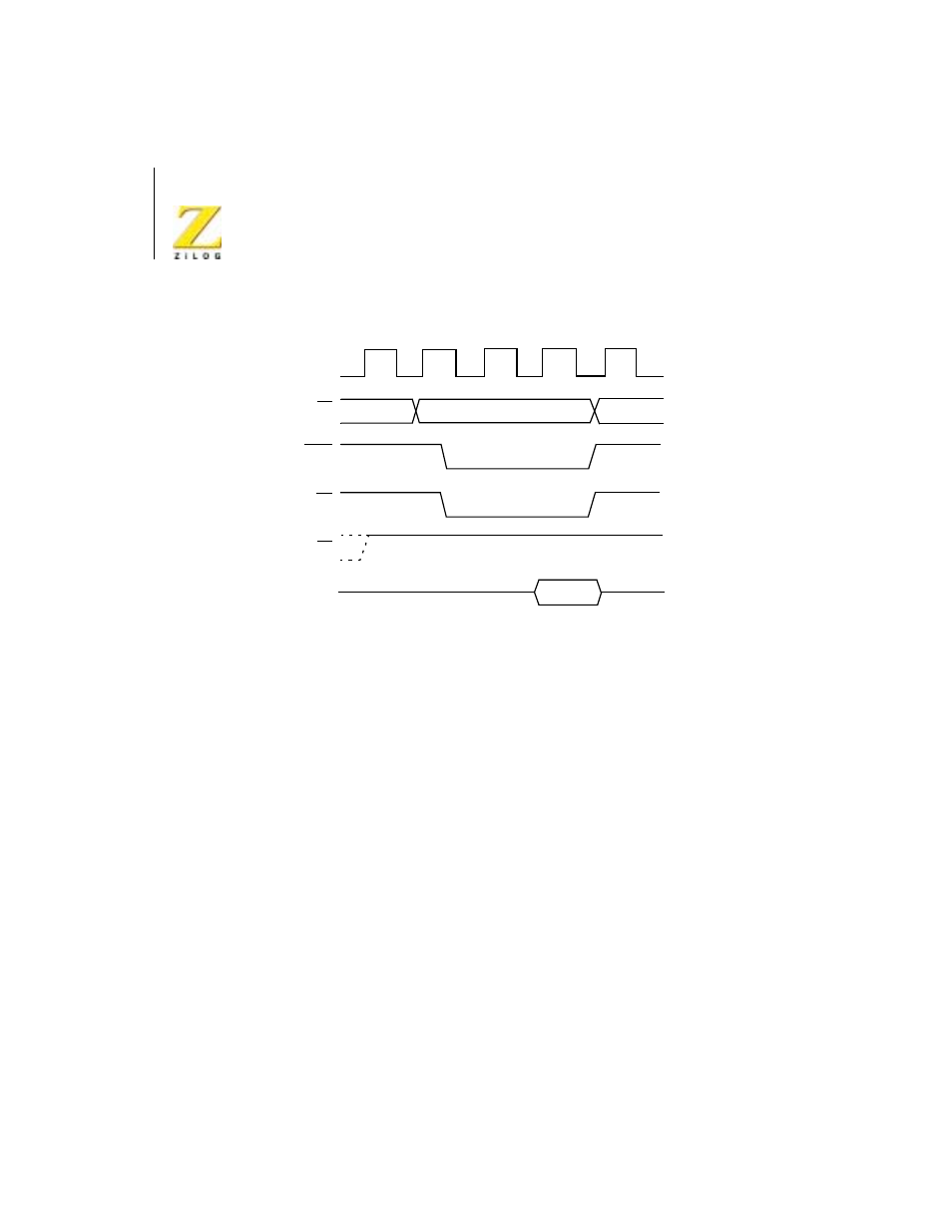
Figure 10.
CTC Read Cycle
CTC Counting and Timing
Figure 11 illustrates the timing diagram for the CTC Counting and Timing
modes.
In the Counter mode, the edge (rising edge is active in this example) from
the external hardware connected to pin CLK/TRG, decrements the down-
counter in synchronization with the System Clock
Φ. This CLK/TRG pulse
must have a minimum width and the minimum period must not be less than
twice the System clock period. Although there is no setup time requirement
between the active edge of the CLK/TRG and the rising edge of
Φ, if the
CLK/TRG edge occurs closer than a specified minimum time, the
decrement of the down-counter will be delayed one cycle of
Φ.
Immediately after the 1 to 0 decrement of the down-counter, the ZC/TO
output is pulsed true.
In the Timer mode, a pulse trigger (user selectable as either active High or
active Low) at the CLK/TRG pin enables the timing function on the second
succeeding rising edge of
Φ. As in the Counter mode, the triggering pulse is
CS0. CS1, CE
IORQ
RD
M1
DATA
Channel Address
T
1
T
1
T
2
T
WA
T
3
CLK
OUT