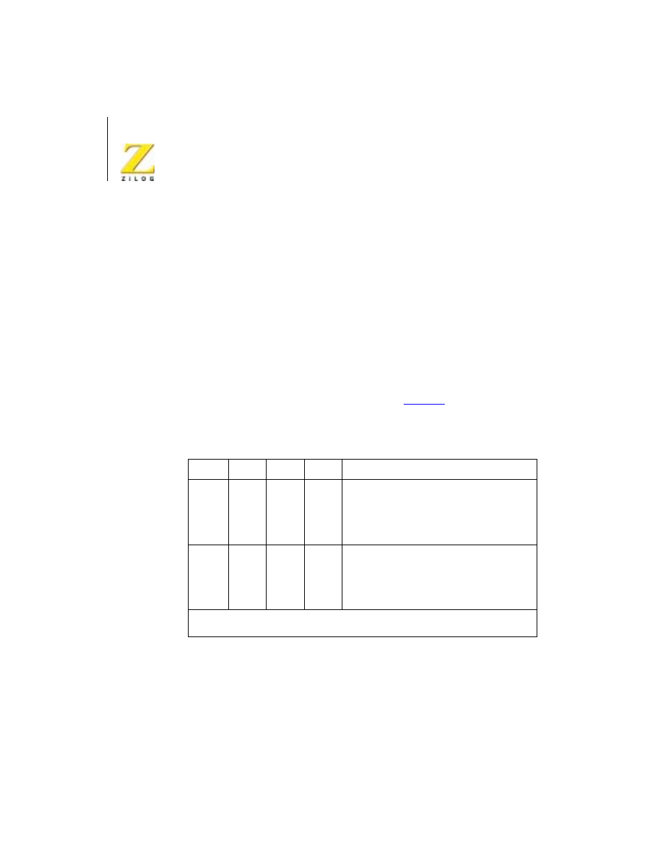
Table 35, Vector results – Zilog Z08470 User Manual
Page 298

< %27 2GTKRJGTCNU
7UGT /CPWCN
UM008101-0601
Serial Input/Output
278
detection and termination, or at the beginning of CRC or sync character
transmission when the Transmit Underrun/EOM latch sets.
Transmitter Interrupt Enable (D1)
If enabled, interrupts occur whenever the transmitter buffer becomes empty.
Status Affects Vector (D2)
This bit is active in Channel B only. If this bit is not set, the fixed vector
programmed in WR2 is returned from an interrupt acknowledge sequence.
If this bit is set, the vector returned from an interrupt acknowledge is
variable. Table 16 describes the vector results.
describes the
Receive Interrupt modes.
Receive Interrupt Modes 0 and 1 (D3 and D4)
Used together, these two bits specify the various character-available condi-
tions. In Receive Interrupt modes 1, 2, and 3, a Special Receive Condition
can cause an interrupt that modifies the interrupt vector.
Table 16. Vector Results
V3
V2
V1
Result
Ch B
0
0
0
Ch B Transmit Buffer Empty
0
0
1
Ch B External/Status Change
0
1
0
Ch B Receive Character Available
0
1
1
Ch B Special Receive Condition*
Ch A
1
0
0
Ch A Transmit Buffer Empty
1
0
1
Ch A External/Status Change
1
1
0
Ch A Receive Character Available
1
1
1
Ch A Special Receive Condition*
Note: *Special Receive Conditions: Parity Error, Rx Overrun Error, Framing Error, End-
of-Frame (SDLC).
