Input mode (mode 1), Figure 90. mode 0 (output) timing – Zilog Z08470 User Manual
Page 213
< %27 2GTKRJGTCNU
7UGT /CPWCN
UM008101-0601
Parallel Input/Output
If the PIO is not in a reset state, the output register may be loaded before
Mode 0 is selected. This allows the port output lines to become active in a
user-defined state.
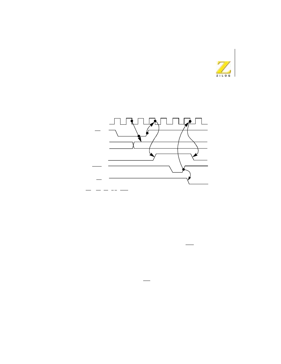
Figure 7.
Mode 0 (Output) Timing
Input Mode (Mode 1)
Figure 8 illustrates the timing of an input cycle. The peripheral initiates this
cycle using the strobe line after the CPU has performed a data read. A low
level on this line loads data to the port input register and the rising edge of
the strobe line activates the interrupt request line (INT) if the interrupt
enable is set and this is the highest priority requesting device. The next
falling edge of the clock line (
Φ) resets the Ready line to an inactive state,
signifying that the input register is full and further loading must be inhibited
until the CPU reads the data. The CPU, in the course of its interrupt service
routine, reads the data from the interrupting port. When this occurs, the
positive edge from the CPU RD signal raises the Ready line with the next
low going transition of
Φ, indicating that new data can be loaded to the
Strobe
Ready
WR*
Port Output
(8 Bits)
INT
WR* = RD • CE • C/D • IORQ
Φ