Figure 114. write register 0 – Zilog Z08470 User Manual
Page 294
< %27 2GTKRJGTCNU
7UGT /CPWCN
UM008101-0601
Serial Input/Output
274
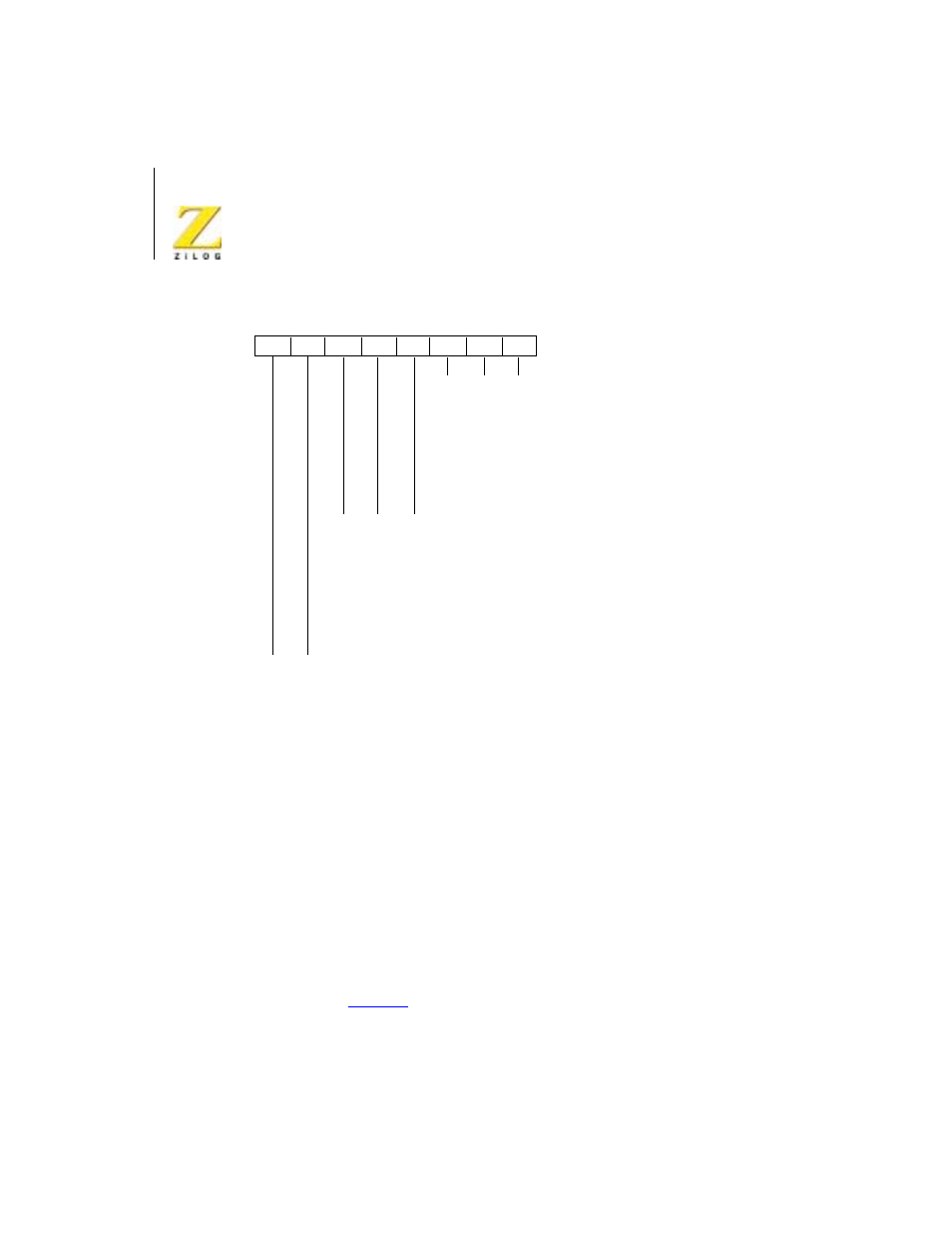
Figure 114. Write Register 0
Pointer Bits (D2-D0)
Bits D2-D0 are pointer bits that determine which write register the next
byte writes to or which read register the next byte reads from. The first byte
written to each channel after a reset (either by a Reset command or by the
external reset input) goes to WR0. Following a read or write to any register
(except WR0), the pointer points to WR0
Command Bits (D5-D3)
Three bits, D5-D3, are encoded to issue the seven basic Z80 SIO
commands (
).
0
0
0
1
1
0
1
1
0
0
0
0
0
1
0
1
0
0
1
1
1
0
0
1
0
1
1
1
0
1
1
1
0
0
0
0
0
1
0
1
0
0
1
1
1
0
0
1
0
1
1
1
0
1
1
1
Null Code
Reset Rx CRC Checker
Reset Tx CRC Generator
Reset Tx Underrun/EOM Latch
Register 0
Register 1
Register 2
Register 3
Register 4
Register 5
Register 6
Register 7
Null Code
Send Abort (SDLC)
Reset Ext/Status Interrupts
Channel Reset
Enable INT on Next Ax Character
Reset TxINT Pending
Error Reset
Return from INT (CH-A Only)
D7
D6
D5
D4
D3
D2
D1
D0