Write register 5 group, Figure 44. write register 4 group, Figure 44 – Zilog Z08470 User Manual
Page 121
< %27 2GTKRJGTCNU
7UGT /CPWCN
UM008101-0601
Direct Memory Access
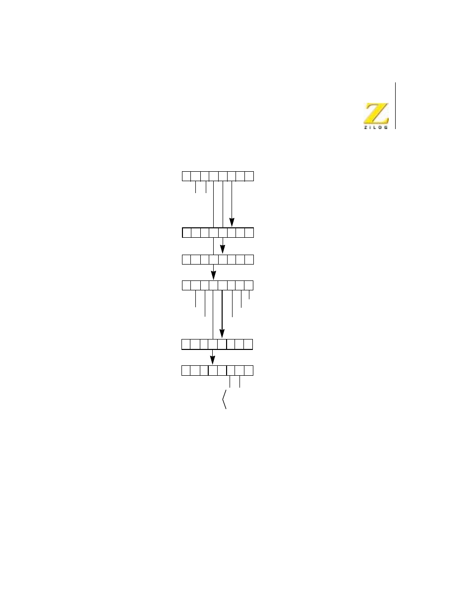
Figure 44.
Write Register 4 Group
Write Register 5 Group
Bits 7, 6, 2, 1, and 0, illustrated in Figure 45, specify the base register byte
for this one register group. The byte is used to specify these characteristics:
D7 D6 D5 D4 D3 D2 D1 D0
Base Register Byte
0
0
0
0
= Interrupt on End-of-Block
= Interrupt on Match and End-of-Block
= Interrupt on RDY
0
1
1
Port B Starting Address
Pulse Control Byte
Interrupt on RDY = 1
Status Affects Vector = 1
1 = Pulse Generated
Interrupt Vector
0
0
0
0
Modified as shown only if
Status Affects Vector bit is set
Vector is automatically
1 = Interrupted at End-of-Block
1 = Interrupted on Match
0
Interrupt Control Byte
(High Byte)
Port B Starting Address
(Low Byte)
0
1
0
1
0
0
1
1
Continuous =
Burst =
Do Not Program =
Byte =
= Interrupt on Match