Side read operation – Altera ALTDQ_DQS2 User Manual
Page 87
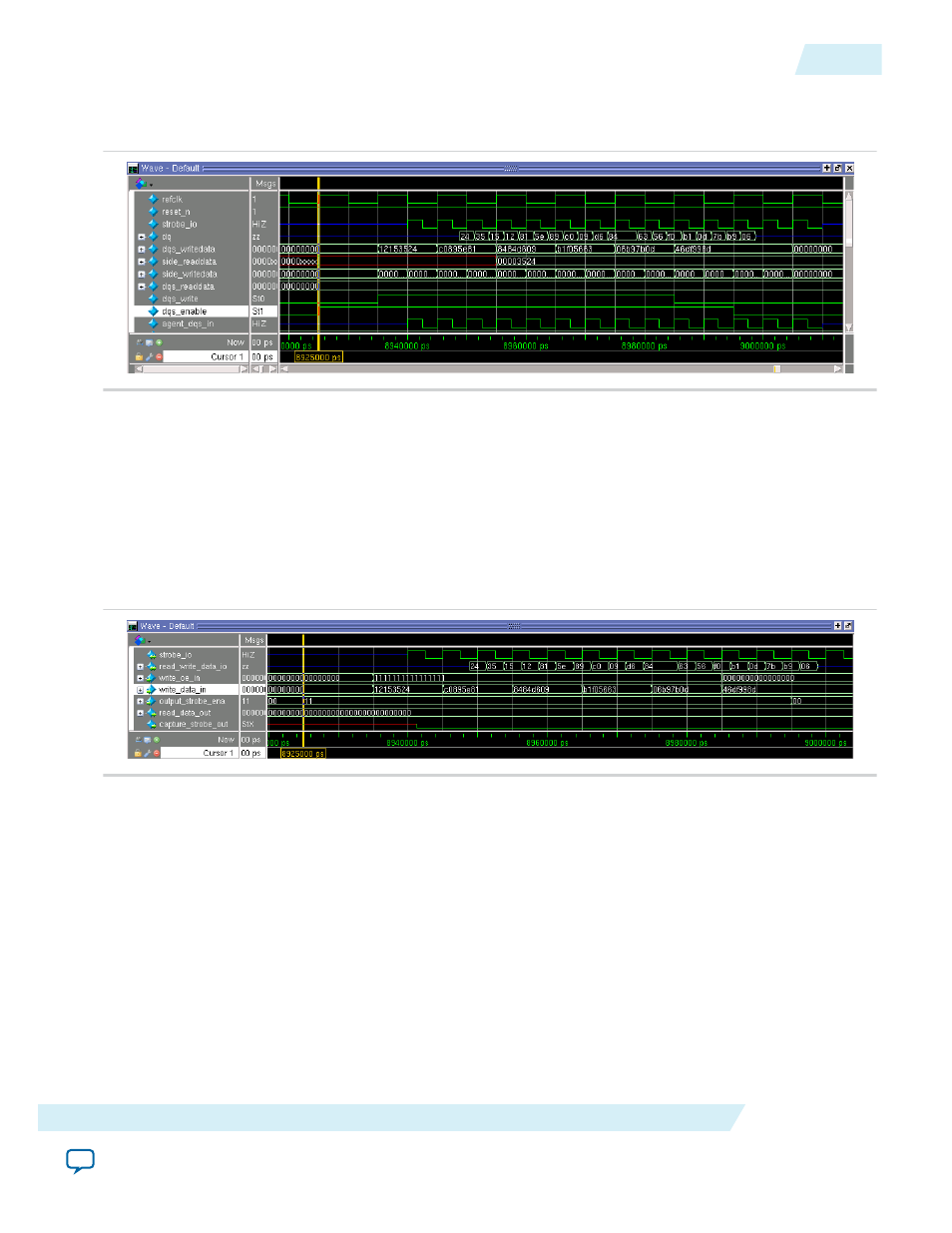
The following figure shows the DQS write operation waveform.
Figure 57: DQS Write Operation Waveform
Note: Before and after the DQS write operation, the
strobe_io
signal is in Hi-Z mode.
The following figure shows the waveform for the dynamic configuration simulation generated after
executing topwave.do (located in the simulation/modelsim folder). The
output_strobe_ena
is held high
from 8.925 us to 8.995 us while the
strobe_io
signal starts toggling only between 8.94 us and 9.01 us. The
write_oe_in
signal is held high throughout the five sets of valid
write_data_in
, which is between 8.935
us and 8.955 us. Center-aligned output data appears on the
read_write_data_io
signal between 8.949 us
and 8.999 us.
Figure 58: DQS Write Operation Waveform After Executing the topwave.do File
Side Read Operation
The side read operation is performed between 9.075 µs and 9.125 µs, in which the DQS agent sends data
to the DQS driver with the
side_readdata
signal. Data validation is carried out in parallel, by comparing
the
side_readdata
signal against the content of the
checkfifo
(data which was written out during the
DQS write operation). If there is a mismatch, the software generates an error message.
The following figure shows the waveform for the side read operation.
UG-01089
2014.12.17
Side Read Operation
87
ALTDQ_DQS2 IP Core User Guide
Altera Corporation